
LM3914
The heart of this circuit is the LM3914 from National Semiconductor. It’s a versatile device that can detect voltage levels and display them through LEDs, either in dot mode or bar mode. You can cascade multiple LM3914s together for an extended display by connecting them externally. The IC operates within a wide supply voltage range (3V to 25V DC), and the brightness of the LEDs can be adjusted via an external resistor. The LM3914's LED outputs are compatible with both TTL and CMOS systems.
Description
In the circuit diagram provided, LED D1 indicates the voltage level in either dot or bar graph mode. Adjusting the resistor R4 connected to pins 6 and 7 of the IC controls the brightness of the LEDs. The potentiometers forming resistor R1 and R2 create a voltage divider network that allows for calibration purposes.
This particular circuit is designed to monitor voltages between 10.5V and 15V DC. To calibrate it, connect the circuit to a 12V DC power source. Adjust the 10K potentiometer so that LED10 lights up in dot mode or glows in bar mode. Next, reduce the sensitivity until only LED1 glows at 10.5V. Switch S1 lets you toggle between dot and bar modes; when closed, it connects pin 9 to the positive supply, enabling the bar graph mode. When open, it disconnects pin 9 from the positive supply, switching to dot mode.
A modified version of this circuit can monitor other voltage ranges. Simply remove resistor R3 and connect the input directly to the upper layer. Adjust potentiometer R2 until LED10 lights up in dot mode, then reduce the lower voltage threshold and reconnect the input. Add a high-value pot (e.g., 500K) in place of R3 and adjust until LED1 lights up individually. Measure the DC resistance and ensure it matches the resistance of R3. Your horizontal display is now calibrated.
Battery Diagram Using LM3914 Circuit
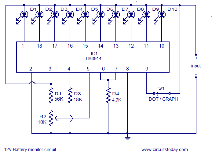
Battery Indicator Circuit Using LM3914
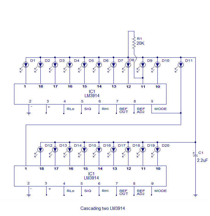
Cascading Two LM3914s
Two or more LM3914 chips can be connected together to create a longer LED voltage level indicator. Below is an example of two cascaded LM3914s creating a 20-LED voltage level indicator.
Cascading Two LM3914s
Other Battery Level Monitoring Circuits You Might Find Useful
1. Simple Battery Level Indicator: This circuit monitors a 3V battery. Based on the Panasonic MN13811G, it uses a CMOS voltage sensor IC. When the LED D1 starts flashing, the battery voltage has dropped below 2.4V.
2. 3-LED Battery Level Indicator: This circuit uses three LEDs to indicate the voltage level of a 12V car battery. At 11.5V, all three LEDs light up, at 13.5V, only one LED remains lit, and between these values, the others illuminate accordingly.
3. Flashing Battery Monitor: This circuit works with 6 to 12V batteries. By adjusting a potentiometer, a transistor-based circuit can make the LED flicker to indicate voltage levels.
Embed Barcode Module,Mini Auto-Scanning Module ,Auto-Scanning Module ,2D Scanner Barcode
Guangzhou Winson Information Technology Co., Ltd. , https://www.barcodescanner-2d.com