
This article refers to the address: http://
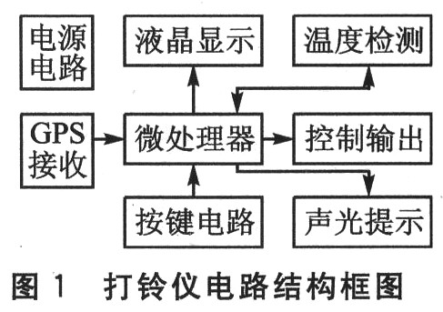
Introduction For a long time, the commonly used bell-type meters in schools, factories and other units have used MCU timing. The timing error is 0.5 s per day. The error will be several minutes or even more than ten minutes, which will cause inconvenience to management. In recent years, the scale of universities and enterprises has been continuously expanding, and enterprises and institutions in many campuses and multi-factory areas have been increasing. These schools, enterprises and institutions strongly demand that the multi-school districts, multi-factory areas, and the commute to and from work should be synchronized, but the actual situation is extremely difficult to synchronize due to the error of the existing bell-type instrument. The intelligent ringing instrument based on GPS signal receiving and PIC microcontroller proposed in this paper has precise travel time and minimal error. As long as the ringing time of the multi-campus and multi-factory enterprises is the same, the ringtones can be kept synchronized with an error of less than 1 s.1 Ringer hardware design The circuit block diagram of the belling instrument introduced in this paper is shown in Figure 1. It is mainly composed of power circuit, microprocessor, GPS receiver, button circuit, liquid crystal display, temperature detection, sound and light prompt, and control output circuit.
1.1 GPS receiving circuit GPS (Global Positioning System) is developed in the United States from the 1970s. It lasted for 20 years and cost 20 billion US dollars. It was built in 1994; it has sea, land and air. A new generation of satellite navigation and positioning system for all-round real-time 3D navigation and positioning capabilities. GPS has all-weather, high-precision, automatic, high-efficiency and other significant features, with powerful functions such as positioning navigation, timing calibration, precision measurement and many other aspects.
The design scheme uses the GPS receiving circuit to receive and demodulate the GPS signal, and extracts the time signal therefrom as the time reference of the belling instrument. Because the time in the GPS signal is generated by the cesium atomic clock, the time precision is extremely high, so the timing accuracy of the bell meter can be high, and the timing error is much less than 1 s. The GPS receiving circuit is shown in Figure 2. It consists of a GPS antenna and a GPS module.
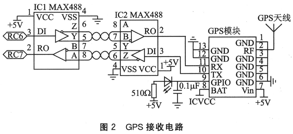
The GPS antenna receives the high frequency signal of 1 575.42 MHz and sends it to the GPS module for low noise amplification and frequency conversion to the intermediate frequency signal. The intermediate frequency signal is sampled and quantized and converted into a digital intermediate frequency signal; the digital intermediate frequency signal enters the relevant channel. After processing, the navigation message is interpreted; the microprocessor in the GPS module receives the navigation message data, and performs corresponding processing to serially output positioning, time, speed and other information.
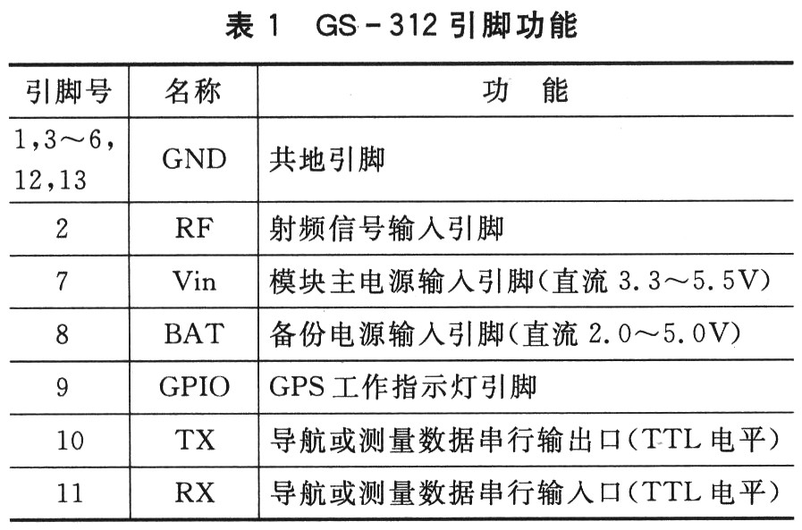
The GPS module uses the GS-312. The baseband processing in this module uses SiRF's Star III architecture chipset. The chipset is equipped with 200,000 correlators with a receiver sensitivity of -159 dBm and low power consumption. The function of each pin of this module is listed in Table 1.
The 8 feet of the GS-312 should be connected to an external battery. If the battery is not connected, the GS-312 is cold-started when the system main power is turned off, and the GS-312 is cold-started. It receives the GPS signal for the first time and successfully outputs the positioning time information for up to 42 s. If the battery is connected, the system master When the power is turned off and the power is turned back on, the GPS module is hot-started. It takes only 1 s to receive the GPS signal for the first time and successfully output the positioning time information.
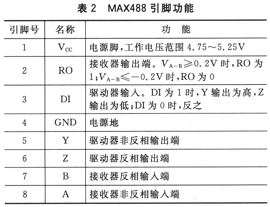
In some applications, the distance between the GPS antenna and the system board is far enough to receive the GPS signal. Therefore, the RS422 standard is used to transmit the GPS demodulated output signal over a long distance. The circuit is shown in Figure 2. In the specific project, the IC2 and GPS modules are separately fabricated into an outdoor unit, and connected to the IC1 and the power supply of the indoor main circuit through an eight-core cable. RS422 is the "Electrical Characteristics Standard for Balanced Voltage Digital Interface Circuits" recommended by EIA. This standard was developed to improve RS-232C and is compatible with RS-232C. It features balanced transmission and differential reception. Among them, two signals are used for transmitting and receiving one signal, and the signal ground is not used at all, and the data transmission is farther, and the anti-interference ability is stronger. Maxim's MAX488 transceiver chip meets RS-232, RS-422, and RS-485 communication standards. The chip contains one driver and one receiver, while having low power consumption, single +5 V power supply, and driver overload protection. It does not require external components, and its common-mode input voltage ranges from -7 to +12 V, making it widely used. The pin functions of the MAX488 are listed in Table 2.
The MAX488 converts the logic level into a potential difference signal through the transmission line driver to complete the information transmission at the initial end, and converts the potential difference into a logic level through the transmission line receiver to realize terminal information reception, which can improve the anti-interference ability of the system and Transmission distance. In Figure 2, IC1's driver inverting output (6Z) and non-inverting output (5Y) are connected to the IC2 receiver inverting input (7B) and non-inverting input (8A), while the IC1 receiver is used. The inverting input (7B) and the non-inverting input (8A) are connected to the driver inverting output (6Z) and the non-inverting output (5Y) of IC2 to form a full-duplex communication over a long distance. The circuit has a communication rate of up to 0.25 Mbps and an experimentally reliable communication distance of more than 20 m.
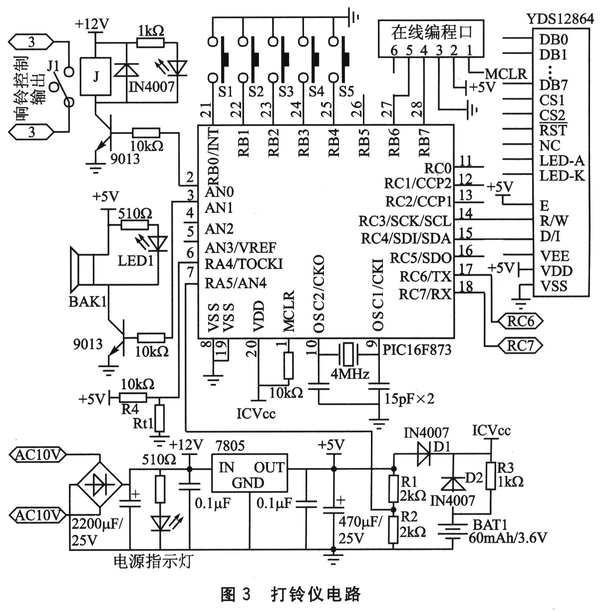
1.2 Other hardware circuits The microprocessor uses Microchip's PIC16F873. The chip uses a 14-bit RISC instruction system, with abundant on-chip resources, including A/D converter, EEPROM, etc., which eliminates the need for an external A/D conversion circuit and EEPROM chip, which simplifies the system circuit. The chip also supports online programming, making it easy to debug and upgrade software. The power supply circuit in the ringer circuit of Figure 3 contains a backup power supply consisting of a 60 mAh rechargeable battery. The microcontroller can determine whether the main power supply is powered down by the voltage divider of R1 and R2. When the main power supply has power, the 5 V DC voltage is supplied to the GPS receiving module and the single-chip microcomputer through D1, and the battery BAT1 is supplied with trickle charge after R3 current limiting; when the main power supply is powered off, the battery BAT1 is received by the single-chip microcomputer and GPS after D2. The module is powered to ensure that the system can still go normally when the system mains power is lost, but the system stops other functions. The divided voltage of R4 and the thermistor Rt1 changes with the change of the ambient temperature. The MCU performs A/D conversion on the divided voltage, and then the table can measure the ambient temperature. The buzzer BAK1 and the light-emitting diode LED1 are sound and light prompts for pressing the button and outputting the ring. The MCU control relay J1 determines whether the external bell is ringing. The internal pull-up resistors of the five I/O pins of the button are turned on. The liquid crystal display module YDS12864 is connected to the single-chip microcomputer through a serial port, and displays the current year, month, day, hour, minute, second, week, temperature and other information in the Chinese mode and the prompt information when the system is set.
2 bell instrument software design
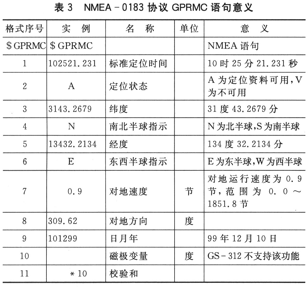
2.1 GPS Protocol The serial output data format of almost all GPS receiver modules follows the standard specifications specified by the National Marine Electronics Association (NMEA). This standard establishes communication standards for all marine electronic instruments, including the format of the transmitted data and the communication protocol for transmitting the data. The NMEA protocol has three types: 0180, 0182, and 0183. 0183 can be considered as the first two supersets and is now widely used. The data format of the NMEA-0183 protocol is 1 start bit, 8 data bits, 1 stop bit, no parity, and the baud rate is 300, 600, 1 200, 2 400, 4 800, 9 600, 19 200; The output data is ASCII code, and the statements include GPGGA, GPGLL, GPGSA, GPRMC, GPGSV, GPVTG, etc., and the contents of each statement are different. The output format of the GPRMC statement containing the year, month, day, hour, minute, and second data is: $G-PRMC, <1>, <2>, <3>, <4), <5>, <6>, <7>, <8> , <9>, <10>, <11>. The end of the frame data is indicated by "LF". For example: $GPRMC, 102521.231, A, 3143.2679, N, 13432.2134, E, 0.9, 309.62, 101299,, *10. The specific meaning is listed in Table 3.
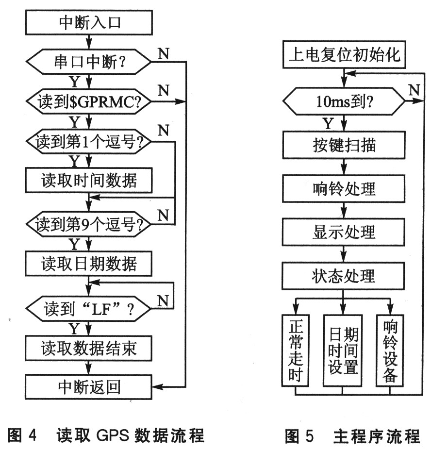
2.2 GPS data reading GS-312 updates the output data once per second, which can be read by serial port interrupt mode. The contents of each statement in the NMEA-0183 protocol are separated by commas. The time data and date data can be identified by judging the number of commas. The flow is shown in Figure 4.
2.3 Main program design The main program flow of the bell-belling instrument is shown in Figure 5. The program structure adopts the scattered structure. The structure has strong anti-interference ability, and the program can automatically re-enter. The button subroutine has a long press function, which is convenient for quick setting by setting the long press function when setting the ring time. The user can press and hold the instant ring button to achieve instant ringing to avoid accidental ringing.
3 Note on the design of the bell device The PCB design of the antenna part is very important, which is directly related to the reception effect of the GPS signal. This design uses a passive antenna. A PCB trace before the signal received by the antenna enters the RF pin of the GPS module requires a matching impedance of 50Ω. GPS module GPS-312 serial output default baud rate of 4 800, usually, the baud rate meets the demand. The GPS module GPS-312 output time is GMT and should be converted to Beijing time, which is 8 in the hour of the GS-312 output time. It should be noted that during the time between 16:00 and 24:00 GMT, the time format change after 8 is added, and the date is increased by 1.
Conclusion The GPS time-based ringer has been mass-produced. The user has proved that the machine is accurate, easy to use and friendly to human-computer interaction. The disadvantage is that in the case where the GPS signal is not received, the crystal frequency division timing has the same timing error as the ordinary bell-type instrument. This design uses the RS422 protocol to transmit the signals received by the GPS over a long distance. As long as the outdoor unit is placed in an open area, the problem of not receiving the GPS signal can be better solved. With a slight improvement, this solution can be easily applied to perpetual calendar or time controllers with extremely accurate travel time. The time controller can conveniently realize multi-machine synchronous control. It can be seen that this program has certain promotion value.
Hair Twist Sponge/Magic Hair Twist Sponge
Product Description:
1. 100% brand new and high quality
2. Twist hair brush sponge3. Like nudred or magic twist brush
4. Great way to get dreads and twists!
5. Save money and time by using this great new styling product.
6. Material: EVA + Sponge

Hair Twist Sponge,Hair Curly Sponge,Men Hair Curly Sponge,Women Hair Curly Sponge
Shenzhen Greater Industry Co., Ltd. , http://www.szgreater.net