
Electric heating ovens have a wide range of applications in industries, agriculture, hospitals, and scientific research. Now a large proportion of electric oven temperature control systems still use discrete components, as shown in Figure 1. The principle of controlling the temperature is as follows: the operator first switches the switches SA1 and SA2 to the on position, and reads the temperature displayed by the mercury thermometer inserted at the bottom of the oven after a period of time, and the temperature inside the oven to be displayed is close to the process temperature. Switch SA2 is opened and the oven is operated by controlling the on and off of KM1. The operator also needs to constantly observe the mercury thermometer. If the thermometer shows that the temperature is different from the process temperature, the operator must constantly adjust the regulator knob until the thermometer's steady state reading is exactly equal to the process temperature. Under normal circumstances, it takes a long time to adjust the process temperature of the crucible, and the error is large. The most important is that due to the aging of the device, the oven temperature control system often fails, and the temperature control system is difficult to repair in the event of a failure. Therefore, it is necessary to remodel or redesign the discrete element electric oven temperature controller system.

Figure 1 Electrical schematic of an electric oven discrete component
1 main circuit
1.1 Analysis of main loop circuit
The electric oven produced this time is mainly used to bake soft film, and its baking process has the following two requirements: The first is that the heating rate is large, so that the oven temperature can be quickly raised from room temperature to the rated load. The process temperature (ie, the set temperature on the tem- perature); the second is when the process temperature is kept warm, the temperature error is small, so as to avoid the phenomenon of under-firing or over-burning of the product. In order to meet the process requirements, two heaters are designed in this scheme. When the temperature rises, the two groups of heaters are put into operation at the same time; in the heat preservation, only the first group of heaters EH1\EH2 and EH3 work. The main circuit circuit diagram shown in Figure 2. When calculating the power of the heater, the power of the same group should be the same, which can prolong the contact life of the contactor and reduce the drift of the neutral point. At the same time, the power of each group of heaters should be based on the rated load of the oven and the maximum operating temperature. , heating cavity volume, heating rate and other factors are calculated, the specific value can be calculated according to the empirical formula
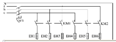
Figure 2 main circuit diagram
1.2 Connection of heating elements
Although there are only two star-connected heating elements connected to the neutral busbar of the power distribution cabinet in this design, the total number of connection terminals for heating elements is still relatively large. In the heating system, if the main circuit does not connect well, the contact resistance at the connection terminal will increase, which will increase the thermal power at the connection terminal. Eventually it will cause the nichrome wire to melt at the connection terminal due to overheating. The thermal power is calculated according to an empirical formula.
Iron screws and galvanized screws, which are commonly used to connect oven heating wires, are prone to oxidation and cracking during oven heating. When the screw oxide layer and cracking site are peeled off, the connection point of the heating wire is increased due to the gap and the contact resistance is increased. As a result, the entire oven heat power is reduced, even causing the arc to melt and heat the main circuit. In order to reduce the probability of the above-mentioned accident, a stainless steel screw is used to crimp the heating wire. The actual operation results show that the failure rate of the fuse at the crimped joint after the use of stainless steel screws is significantly reduced.
1.3 Measures to Prevent Short-Circuit Heaters
Although the main loop of the oven is relatively simple, the improper installation, use, and maintenance of the heating elements can result in phase-to-phase shorting between the heated nichrome wires or a short circuit between the nichrome wire and the oven housing. In order to minimize the possibility of a short circuit in the main circuit, the following two issues should be addressed for the actual conditions of the oven.
The first is that the six phase wires and one neutral wire from the output terminals of the main contacts of the contactors KM1 and KM2 must be led through the same threading hole to the connection terminals at the bottom of the oven. Therefore, the seven copper wires must be properly handled and Their insulation between the oven shells is particularly important. Before the crimping of the copper conductors, adequate ceramic insulators should be laid for each conductor; when the conductors are perforated, crossovers should be avoided and, in addition, the excess copper conductors cut. In this way, the probability of a short circuit at the perforation line is greatly reduced.
The second is the nichrome wire placed in the groove. If the nichrome wire is placed outside the groove, its energized heating is very likely to be connected to the oven housing through the iron cover plate to cause a short circuit or a short circuit with other nickel-chromium wires. The solution is to connect the main circuit and control circuit wires and confirm that the connection is correct. Do not cover the cover plate for heating. The nichrome wire will become soft when heated. Use insulated needle-nose pliers and screwdrivers. Place the nickel-chromium wire placed in the outside of the oven plate into the groove. After power-off and cooling, confirm that all the nickel-chromium wire is in the groove. Cover a lid with a few ceramic plates and then cover the cover. Prevent nickel-chromium wire from short-circuiting.
1.4 clean the oven in time
Considering that the heat production in the oven making and the oven is mainly convection, the heating elements of the oven are basically installed at the bottom. During the heating process of the oven, the surface of the iron plate placed above the heating element for shielding is more easily oxidized due to heat than normal temperature, and these oxides are cracked in a sudden quenching process such as oven heating and natural cooling. On the hob. Although the iron oxide is non-conductive, long-term accumulation of iron oxide swarf in the recess of the furnace tray will cause the nickel chrome wire to overheat and fuse due to the inability of heat to dissipate. To solve this problem, the best solution is to use stainless steel liners and utensils in the oven. Otherwise, the hobs must be regularly cleaned to prevent the accumulation of large amounts of iron oxide scraps.
2 control loop
2.1 Circuit Analysis of Control Loops
The oven temperature control system designed this time belongs to the contactor control. The whole system is based on the XMT temperature controller produced by Wuhan Huida Industrial Control Technology Co., Ltd., with three switches, two AC contactors, a time relay and a platinum heat. resistance.
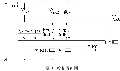
2.2 Application of Instrument Over Temperature Alarm Output Terminal
Under normal circumstances, temperature controller over-temperature alarm is mainly used in two ways: the first is over-temperature sound and light alarm, that is, when the alarm is over temperature, normally open terminal is closed, and the over-temperature indicator and alarm bell are controlled directly or through a relay; Use the over-temperature alarm normally closed output terminal to disconnect when over temperature, cut off the main contactor in the relay control system or block the trigger pulse in the thyristor control system.
3, the conclusion
After the oven temperature control system was installed and commissioned in 2003, despite frequent use, no other failures occurred other than the replacement of nickel-chrome wires. The system has the advantages of simple structure, high control accuracy, low failure rate, low cost, and easy acceptance by operators, and therefore has great promotion value.
![]() Wuhan Huida Industrial Control Technology Co., Ltd.
Wuhan Huida Industrial Control Technology Co., Ltd.
——————————————————————————————————
One-stop solution provider for heat treatment automation
phone
Fax /
Website:
Address: A, Building A, Building 1, Huifeng Enterprise Headquarters, Gutian Second Road, Qiaokou District, Wuhan