
0 Introduction
This article refers to the address: http://
Diabetes is a common metabolic endocrine disease caused by the lack of insulin or its receptor abnormalities in humans. It is characterized by hyperglycemia and is a worldwide epidemic disease. In recent years, its incidence has shown a significant upward trend, and currently about 10% of adults worldwide suffer from this disease [1]. In China, there are about 40 million people with diabetes. The current treatment is mainly to regulate the metabolism of glucose in patients. The important basis for clinical treatment is the blood glucose level of patients. Therefore, it is important to track and evaluate the control of diabetes by self-monitoring the blood glucose meter. In particular, the self-monitoring blood glucose meter can conveniently and quickly detect the result in the hospital or even at home. At present, the blood glucose meter product can only give the blood sugar level, and the patient has to adjust the treatment plan and diet control according to this. In addition, there are insufficient test accuracy and test range. Therefore, it is of great significance to study high-precision and intelligent blood glucose monitoring instruments.
1 Detection principle
The large-scale detection instruments used in clinical diagnosis are large in size, expensive, and cumbersome in detection process. They are not suitable for long-term self-monitoring of small and medium-sized hospitals, emergency departments and patients. The practical use of enzyme electrodes in biosensors has been rapidly improved. Enzyme electrodes such as glucose, lactic acid, cholesterol, urea, and amino acids are being widely used in medical testing. One common feature of these sensors is the use of molecular recognition capabilities of biological materials such as microorganisms, enzymes, and antibodies, and the use of biological materials as sensors for molecular recognition components; and then the use of electrons generated by the reaction of the detected substances contained in the sample solution with the enzymes. The electron acceptor is reduced, and the measuring device uses an electrochemical method, that is, measures the amount of reduction of the electron acceptor, and performs quantitative analysis of the detected substance.
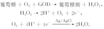
The detection principle of the instrument is based on the solidification of glucose oxidase (GOD) on the surface of the electrode. When the blood drops into the blood glucose test electrode, a redox reaction occurs, and the ferrous ions in the transport medium lose electrons during the reaction. Oxidation reaction, glucose oxidase oxidizes glucose to form H2O2 and gluconic acid, H2O2 oxidizes ferrous ions, electron gain and loss occurs during redox process, and an oxidation current is formed under a certain voltage. The purpose of detecting blood glucose concentration is achieved by detecting that the current change is approximately linear with the glucose concentration. The specific reaction equation is as follows:
2 Instrument design and implementation
2.1 Hardware Structure
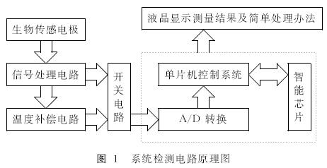
The whole instrument system is composed of enzyme electrode sensing part, signal conditioning (current and voltage conversion, amplification and filtering part), temperature compensation part, liquid crystal display part, single chip microcomputer and smart chip, as shown in Fig. 1. The micro-current generated by the blood drop after the enzyme electrode is small, can only reach the micro-ampere level, is not convenient for measurement and analysis, so it is first converted into a voltage signal, and then subjected to voltage amplification. Since the system noise generated by the power supply and various factors interferes with the test accuracy, the filter circuit should be designed to remove the interference signal, making the test more accurate. The processed voltage value is transmitted to the MSP430 of the built-in A/D conversion MCU, and the MCU calculates the concentration value of the blood glucose, and then displays the result using the liquid crystal.
2.2 Main test process
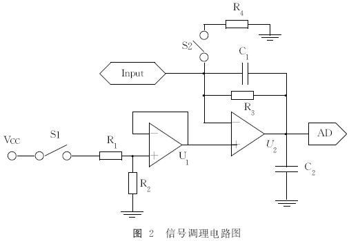
The signal conditioning circuit in the detection system is shown in Figure 2. After the instrument is powered on, the MCU controls the multi-way switch S1 to close, and the preamplifier input is the R1 and R2 divider values, which is set to 0.4V. According to the follower and the ideal op amp characteristics, the output of the latter stage is also 0.4V at this time. After inputting the MCU through A/D conversion, the control display shows “Please insert the test stripâ€. When the system is inserted into the blood glucose test strip, S2 is closed and R4 is introduced into the circuit. The latter stage op amp constitutes a non-inverting amplifier, and R4 is adjusted so that the circuit output value is 0.6V. After inputting the MCU through A/D conversion, and controlling the display to display “Please drop bloodâ€. The current signal generated after the blood is dropped from the “Input†input, the output voltage signal is abrupt and transformed, and then input to the single-chip microcomputer. After the reaction is completed, the blood sugar level is calculated according to the voltage change and displayed.
2.3 Temperature compensation
Changes in ambient temperature cause measurement drift due to zero drift and sensitivity of the detection system. In order to eliminate the influence of ambient temperature, the temperature compensation circuit in the system is realized by DALLAS single-bus micro temperature sensor DS18B20. The temperature range is -55~+125°C, the measurement resolution is 0.0625°C, and the temperature measurement accuracy is ±0. .5 ° C. The temperature signal is input to the single-chip microcomputer through the multi-way switch, and the CPU automatically corrects the error of the test result according to the temperature characteristic of the blood glucose test electrode.
2.4 Smart chip
In order to further improve the practicability of the instrument and to facilitate the patient as much as possible, the principle of artificial intelligence is introduced in the instrument. The patient can obtain the personal condition information and display simple treatment methods and precautions while detecting the blood glucose concentration. This feature is primarily achieved by calling information from a solidified smart chip with a diabetes knowledge base. The knowledge base solidified in the chip is based on treatment guidelines approved by the World Health Organization, the International Diabetes Federation and the Chinese Diabetes Association, and the guidelines are authoritative in the analysis of diabetes. The patient can select the "reasoning" function on the operator interface after measuring the blood glucose level.
3 instrument performance analysis and testing
3.1 Easy to operate, low power consumption
After the patient is turned on, he only needs to follow the prompts to complete the whole test process. The operation interface is simple and friendly. According to the output voltage of the test conditioning, as shown in Fig. 2, it can be seen that the reaction tends to be stable from about 20 s after the blood drop, and the test time of the patient is not more than 25 s under the correct operation steps. Since the blood collection uses siphon test paper, the single blood collection volume only needs about 3 to 5 μL. Using MSP430 series low-power single-chip microcomputer, the instrument can automatically cut off the power after removing the test paper according to the voltage change during the test, effectively saving energy.
3.2 Wide test range
According to the diagnostic criteria for non-insulin-dependent diabetes mellitus (NIDDW) recommended by the WTO in 1998, blood glucose less than 7mmol/L is non-diabetic (fasting blood glucose 3. 5-7 mmol/L is normal range), 7-11. 1mmol/L For impaired glucose tolerance, greater than 11.1mmol / L for diabetics. After testing different samples, the test range of the instrument can reach 2. 2 ~ 27. 8mmol / L, completely covering the range of possible values ​​of human blood sugar.
3.3 Test data is reliable
In order to verify the true reliability of the blood glucose meter measurement data, clinical tests were conducted in the research laboratory of the First Hospital of Shanxi University. Test samples with different blood glucose concentrations were tested with a smart blood glucose meter and a large Italian biochemical analyzer (BT-3000). The test results show that the two have good consistency, and the error of high blood sugar level is larger than that of hypoglycemia and normal blood sugar, which needs further calibration and calibration. The test values ​​of the large biochemical analysis were taken as standard values, and the results of the 30 groups of tests are shown in Table 1. The regression analysis was performed on the test data, and the fitting results are shown in Fig. 3. The regression equation is
![]()
Where: the regression coefficient b = 0.9851, the intercept a = -0. 0806, the correlation coefficient R = 0.9962, the standard deviation SD = 0.278.
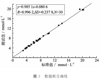
Table 1 Comparison of intelligent blood glucose meter and standard blood glucose value

4 Conclusion
The blood glucose concentration measured by the intelligent blood glucose self-monitoring device has a significant correlation with the high-precision blood glucose meter measurement result, and has the advantages of simple operation, short measurement time, accurate and reliable results, high intelligence, low power consumption, etc., and is optimized and Improvement can be an ideal instrument for diabetic patients to monitor and control their own blood glucose levels in the home.
Click to see the original picture
CCTV Power Supply with battery backup, 4 Channel /9 channel /18 channel 12VDC independent fuse Power Distribution Unit for CCTV camera and Access control Systems .
With battery backup 12V/7Ah, 12V/17Ah for emergency function.
Features:
- Thermal Cutoffs Protection (TCO): each output has independent PTC fuse and LED indicator, when problem occurs, only affect the independent output, other outputs still working.
- Short circuit protection: when short condition occurs, independent PTC fuse will open the circuit, when condition removed, PTC fuse will automatically back to close.
- High voltage protection: when high voltage occurs, the surge protection will be hit through to protect the connected device.
- Over Current protection: when over current occurs, the power supply will automatically switch to self-protection status, when condition removed, then switch back to normal.
Application:
1. Stepping motor
2. PLC control System
3. Surveilance cameras
4. LED advertisement
5. Lamps and lanterns
6. CP communication
7. Communication equipment
8. Industrial control
9. Home Application
10. The traffic and Building
Product Images:

Boxed Power Supply,24V Boxed Power Supply,CCTV Boxed Power Supply, Boxed Power Supply UPS
Dongguan Xiaoerduo Electronics Co., Ltd. , http://www.steadysmps.com