
Summary: Designed a car with automatic round trip and intelligent control. The MSP430F149 is used as the core chip, and the dual full bridge driver chip is selected as the trolley motor drive. The PWM technology is used to dynamically control the motor speed, the infrared photoelectric sensor detects the identification line, and the U-type infrared photoelectric sensor measures the distance. The MCU judges and processes the information returned by various sensors, and issues commands to the motor driver to control the car to achieve automatic acceleration, speed limit, deceleration, braking, reversing, and displaying the travel time and travel distance on the LCD display during the round trip. .
This article refers to the address: http://
Smart car is a multi-disciplinary scientific and creative design that covers the background of automotive electronics, including intelligent control, pattern recognition, sensing technology, electronic and electrical, computer and machinery. The National Electronic Contest and the Provincial Electronic Contest almost every time there is a problem in this aspect of smart cars. All colleges and universities across the country also attach great importance to the research of this topic, which can realize tracking, obstacle avoidance, detecting patches, searching for light, and avoiding Basic functions such as cliffs.
1 overall plan
Design a car that automatically travels between the starting line and the finish line. It starts at the starting line and reaches the finish line for 10 s, then automatically reversing back to the starting line. Accelerate, decelerate, speed limit, brake, and reverse functions are performed within the required runway range. Shows the time and distance of a round trip after parking.
Circuit design block diagram shown in Figure 1, can be divided into MSP430F149, circuit drive module, black line detection module, speed measurement ranging module, display module and other parts.
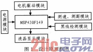
The MSP430F149 is used as the core chip, and the dual full-bridge driver chip L298 is selected as the car motor drive. The PWM technology is used to dynamically control the motor speed. The infrared photoelectric sensor (LTH1550) detects the identification line, the U-type infrared photoelectric sensor measures the distance, and displays the driving on the liquid crystal display. Time, driving distance and other related data. The microprocessor mainly processes the ground detection mark signal returned by the photoelectric sensor and the detection path information returned by the U-type sensor, and issues a command to the motor driver to control the acceleration, deceleration, speed limit, brake, reversing, etc. of the car, in the liquid crystal display. Display related data such as travel time and travel distance.
2 unit module design
2.1 microprocessor module
The main task of the microprocessor is to judge and process the information returned by various sensors, and to issue commands to the motor driver to control the car to achieve automatic acceleration, speed limit, deceleration, braking, and reversing during the round trip, because the car realizes less functions. The microprocessor is selected from the US TI company MSP430 series microcontroller. Because the MSP430 microcontroller has low power consumption, high-speed real-time control and data calculation, and has more on-chip resources for design and use, the design is more concise and more effective.
2.2 Motor drive module
A DC geared motor is used. The DC geared motor has large turning torque, small volume, light weight and simple assembly. It has strong overload capability, can withstand frequent impact loads, and can achieve frequent quick start and reverse; it can meet various special requirements in the automatic round-trip process. It can be conveniently realized to advance, retreat, stop, etc. of the DC geared motor through the single chip microcomputer.
Considering that the car must be able to advance, retreat, stop, and be flexible and specific, the L298 dual full bridge stepper motor dedicated driver chip is selected. The internal 4 channel logic drive circuit can easily drive two DC motors or one two-phase stepper motor. In order to control the rotation speed of the wheel, PWM speed regulation method can be adopted, that is, a series of square waves with fixed frequency are outputted by P1.4 and P1.5 of the single chip microcomputer, and then the motor is driven by power amplification, and the output square wave is changed by programming in the single chip microcomputer. The duty cycle changes the average voltage applied to the motor, which can change the speed of the motor. The combination of the two motor speeds of the left and right wheels can realize the forward, reverse and other functions of the trolley.
2.3 Black Line Detection Module
The principle of black line detection is that light illuminates the road surface and reflects. Since the reflection coefficients of the black line and the white line are different, it is determined whether the black line is reached according to the received reflected light intensity. Considering that the ambient light interference is mainly the DC component, if the control modulation signal with the AC component is used, the external interference can be greatly reduced; in addition, the maximum operating current of the infrared generation tube depends on the average current, if the duty cycle is small. The modulating signal, when the average current is constant, the instantaneous current can be very large (50 ~ 100 mA), which also greatly improves the signal to noise ratio. The design adopts infrared photoelectric reflection sensor. In view of the low chassis, the close-range effective photoelectric sensor (LTH1550) is composed of high-emitting infrared infrared diode and high-sensitivity photoelectric tube. The detection range can be adjusted from 4 to 15 mm; non-contact detection is adopted. In order to reduce the interference of ambient light, it is necessary to adjust the orientation of the sensor so that ambient light cannot directly hit the detector. The optimum detection distance is 6 to 14 mm, and should be kept at a distance of about 10 mm from the ground during installation.
2.4 Speed ​​measuring and ranging sensor
Because the trolley wheel is small, the U-shaped sensor is suitable for high precision occasions, and more black lines can be added to the wheel to meet the accuracy requirements of the pulse counting. U-type infrared photoelectric sensor is used to install the speed measuring code disc on the motor shaft. After the pinion gear is installed, the speed measuring code wheel can be placed under the pinion gear as the photoelectric encoder disk. When the motor rotates, the code wheel rotates. The infrared sensor is used to change the intensity of the light reflected by the objects of different colors, and the conduction and the cut-off of the receiving tube are changed. The received signal is counted with an external interrupt.
The U-shaped sensor can accurately calculate the mileage of the car. Fix the code wheel on the rear wheel of the car and place the U-shaped photoelectric switch on the code plate. The rotating shaft of the motor rotates to drive the speed dial to rotate. The speed dial is engraved with a plurality of slits. When the disc rotates, the emitted light is received by the receiving component through the slit, and the photoelectric switch is continuously turned on and off. In this way, a pulse is obtained at the output of the photoelectric switch, and the received signal is counted by a counter.
2.5 LCD module
The system mainly needs to display various measurement parameters such as running time and mileage of the car. The LCD1602 liquid crystal display is used, and the liquid crystal display module with its own Chinese character library is convenient and beautiful to display, the display information is large, and the display speed is fast. Using the display mode of serial communication, the IO port of the MCU can be greatly saved.
3 analysis of the working principle of the main circuit
The car starts to be placed in a fast forward state, and the infrared sensor LTH1550 detects the ground black line. The signal is transmitted back to the microprocessor through the P1.0 of the single-chip microcomputer, and is judged and analyzed by the processor. According to different signals, P1.4 and P1.5 are obtained. The PWM wave with different duty ratios is driven to drive the motor, so that the car is placed in different forward state, and functions such as automatic acceleration, speed limit, deceleration, braking, and reverse are realized. After returning to the starting line, the microprocessor takes the driving time from its own timing function TBR and displays it on LCD1 602. At the same time, the mileage information detected by the U-shaped sensor is transmitted back to the microprocessor through the P2.3 of the single-chip microcomputer and displayed on the display.
4 Conclusion
The system adopts MSP430F149 and various sensor combination control not only has the characteristics of convenient control, simple system circuit and strong flexibility, but also improves the control precision of the position of the car through the combination of C language programming control and PWM pulse width modulation technology. Constant speed control of low speed section speed.
Smart Air Inflator,Smart Air Pump Bike,Automatic Smart Air Pump,Electric Automatic Smart Air Pump
SHENZHEN SMARTNEWO TECHNOLOGY CO,. LTD , https://www.newopump.com