
It is generally believed that it is more difficult to develop multiprocessor system software than a single processor system. But the actual situation is not always the case. Our design team, working at TRW Conekt, a division of TRW Automotive, recently took over a project that showed how to leverage the power of the problem and develop an efficient system using many processors.
This article refers to the address: http://
Our team received a mission to develop an automotive embedded processing electronics system for a project called “Foot-LITE†(the project was led by MIRA, the UK Government-sponsored Technical Strategy Committee, Ministry of Transport and Institute of Engineering Physics) sponsor). The project provides feedback to the driver and gives them an understanding of their driving habits from a safety and fuel economy perspective.
The system provides feedback to the driver in two ways. First, a dashboard-based smart phone display system (designed by the University of Brussels, developed by HW CommunicaTIons) provides drivers with real-time communication related to events that require immediate attention. Second, the system is also capable of continuously collecting trip data, including special "event" video streams, and then uploading them to an Internet server for users to view during their leisure time. According to the driving advice of our partner, the Institute of Advance Motorists, another partner, Ricardo UK, has developed an algorithm that can determine which events need to be marked to alert users. note.
The project will install the system into a fleet of 30 vehicles. Test drivers were publicly recruited by the project partner Hampshire County Council.
The project will be gradually integrated into the results of collaborative research by 12 industry, government and academic partners. This means we need a very flexible solution to solve our processing problems.
At first we wanted to provide a single processor system. However, it was quickly discovered that dedicated processors can simplify the integration work required for each iteration of algorithm development work.
Basic system
We already have a processor system that is currently being developed in another project, mainly for image processing (Figure 2).
The system is based on a single Xilinx® Spartan®-3A XC3SD3400A device connected to four independent DDR memory blocks. This architecture allows users to implement many different processor/logic configurations. For example, the entire FPGA fabric can be used as a purely logical resource fully defined by HDL. In addition, you can use more advanced tools, such as Xilinx EDK, to implement four (or more) soft-core microprocessors. Each soft-core microprocessor can access its own dedicated DDR storage device to protect data from interference from other microprocessors. For other simple tasks, you can use embedded BRAM blocks to implement more processors.
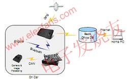
Figure 1 – Foot-LITE System
In addition, a small daughter card can be used to configure external I/O so that custom I/O settings can be quickly converted for different projects.
The project partner decided early on to adopt the USB interface because it added various peripherals to the system. However, this requires some form of USB protocol stack - we get it by using the Petalinux version of uclinux, and a daughter card with a USB host device.
Using Linux also provides us with an easy way to manage SPI flash devices that provide FPGA bitstream and application code storage. We installed a simple JFFS2 file system that can be used for field application upgrades via Ethernet (using FTP) or by booting a USB stick (containing a script to upload new code to internal flash). In traditional embedded systems, all of these requirements require the software team to write the underlying application code. However, with Linux, we can easily write simple Bash scripts to control these processes.
Foot-LITE algorithm
Ricardo developed a core algorithm for evaluating driver behavior and applied it to his rCube rapid prototyping system (http:// Engineering-Consulting/AutomotiveExpertise/Controls- -Electronics/Embedded-Software/rCube/). We conducted a preliminary simulator test using this method and tested it on three test vehicles. On the test vehicle, an embedded vision system (based on existing TRW products - coincident with an FPGA) is used to measure the distance to the vehicle in front and to assess the position of the vehicle in the lane. The test vehicle can also provide distance information via a radar system. As a step before production, we eliminated the radar system in a larger trial because the vision system was already able to provide enough information for the application.
We installed a front-view camera and processing subsystem on the vehicle, which was integrated into a small device that was mounted next to the rearview mirror. The embedded algorithm in the subsystem measures the distance between the body and the edge of the lane through video image processing. In addition, the parallel algorithm can detect the vehicle in front of the Foot-LITE vehicle and measure the head spacing. The subsystem uses the automotive standard Controller Area Network (CAN) bus to transmit data to the Foot-LITE subsystem unit.
We integrated a three-axis accelerometer and yaw rate sensing system in the Foot-LITE unit, which gives the Foot-LITE algorithm the possibility to access high-speed, low-latency vehicle dynamics when needed.
The Foot-LITE algorithm integrates all the data together to give the driver a series of concise information about his (or her) driving style.
Algorithm implementation
At first we wanted to provide a single processor system. However, it was quickly discovered that dedicated processors can simplify the integration work required for each iteration of algorithm development work. We isolate the main processor from the Foot-LITE algorithm processor and use the MicroBlaze? Fast Simplex Link (FSL) bus system to communicate. This completely separates the storage of the two processors (unlike the common shared storage approach), which greatly simplifies the integration because the error does not migrate from one processor to another through memory corruption. .
In addition, this avoids competing for processor cycles. This means that our partners can rest assured that any changes we make to the host application will not affect their application performance.
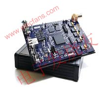
Figure 2 – Spartan-based processing module
We developed a series of wrappers that allow us to access C language programs generated by the SimulinkTM compiler without major changes to the interface. We can provide a small amount of non-volatile on-board cache space through the I2C bus to store various tune parameters in the Foot-LITE algorithm. This requires a simple wrapper so that the algorithm can be easily accessed in the Simulink environment, reading the memory at startup and writing back when it is turned off.
The system needs to measure acceleration and yaw rate and communicate with the lane and vehicle detection system via the CAN bus. Since we already have the underlying CAN driver, and we are concerned that Linux applications measure the timeliness of vehicle dynamics over a 40-ms timeframe, we decided to add another MicroBlaze to the system. This eliminates the need to import the CAN driver into Linux and achieves deterministic performance through another isolated processing node. This is very important for the algorithm because of the dynamic measurements used by the algorithm. In addition, this method allows us to take apart the work of writing software for parallel development. Here we still use FSL as the interface between the dynamic processor and the Foot-LITE algorithm processor.
Video capture and compression
The initial idea of ​​the system is to transmit the data of the vision system to the Foot-LITE algorithm unit via the CAN bus, providing simple measurements for lane width and offset, distance to the vehicle in front, and the like. The project partner decided to enhance its setup by transmitting the captured video frames to the server for offline environmental analysis to translate the meaning of the information provided by the system. Since this requirement is only for "Internet quality" video (300x200 at 5 Hz), we feel that we can use a MicroBlaze to compress the video stream into a series of JPEG images in real time. The image captured by the camera is a wide VGA (720 x 480 pixel at 30Hz) video stream. Obviously, image downsampling should be done to the hardware.
We designed a simple peripheral that performs downsampling by alternately removing pixels and rows to produce a 360 x 240 image. The peripheral also removes 4 frames every 5 frames to achieve the desired frame rate. Visually acceptable results can be obtained without more complex processing, as JPEG processing can make out-of-the-box human effects invisible. We use System Builder to develop this peripheral because it can be exported directly to EDK, and we already have experience with system generators for more complex image processing.
The data entering the SDRAM connected to the JPEG processor is controlled by the bus of the downsampling peripheral, and the data is then compressed frame by frame and sent to the circular buffer until the Foot-LITE algorithm issues a flag. The JPEG processor sends the compressed video frame (also via FSL) to the host MicroBlaze. We used the code base provided by the standalone JPEG team and found that it can work at 5 Hz without any optimization.
In addition, the isolated processor allows another software engineer (in a different location) to be in parallel when developing the same part of the system.
Connect to smart phone and onboard diagnostic system with Bluetooth
Easy installation is a key factor in this project. Reducing the number of cables used in the system is also an important aspect to consider.
We use Bluetooth as the interface to connect to the smartphone. The driver for the standard USB Bluetooth connector is standard on the ucLinux kernel, although we have to build the userspace tool ourselves. These tasks have many dependencies on other code, and these codes are cross-compiled and added to the ucLinux file system via the Petlinux toolkit.
After we selected Bluetooth as the smart phone interface, we naturally chose Bluetooth as the interface to the onboard diagnostic system. We use the standard off-the-shelf Bluetooth-OBD interface module, which saves another wired link from the system.
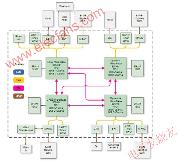
Figure 3 - FPGA Block Diagram showing the main external components
Easy commissioning
Debugging systems with multiple parallel execution threads is often difficult. But dividing the system into multiple processors can make things simple. We don't need a multi-threaded debugger (such as needed to debug multiple processors in a Linux environment). The Xilinx Debugger (XMD) can be connected to multiple processors, and by using TCL (XMD's understandable tool command line language), we can automate the setup and download the code to be tested to multiple processors. on. Of course, you can also use the conventional embedded system debugging method with printf declarations, because each processor has its own serial port.
Another tool of great value when debugging interprocessor communication is ChipScope? Pro. The embedded logic analyzer is built into the FPGA fabric, allowing us to capture data through the FSL link, troubleshoot vulnerabilities that hide deeper defects to the sender or receiver, and then troubleshoot the code line by line.
The significance of isolation using four processors is that when a component is debugged, there is basically no need to debug. This avoids the many problems that arise from the strange interactions when integrating code from different sources into large stand-alone applications, or when running multiple processes on a single processor.
FPGA implementation
This project basically does not involve HDL, and only uses an advanced wrapper to integrate the EDK-based design with a small watchdog code to ensure that the system is turned off after the driver turns off. The EDK generates the main part of the FPGA (the MHS file is longer than 1,300 lines!), and the system generator is responsible for generating the video downsampler. We configured cache and floating point units for all four microcontrollers. After using four processors, four DDR memory interfaces, and a range of peripherals including Ethernet, SPI, IIC, CAN, UART, Timer, and GPIO, approximately 70% of the device's lookup tables are occupied (approximately 28,000 lookup tables). As is often the case with microcontroller-based FPGAs, block memory usage is very high, over 90%, or 119 BRAM, but DSP module usage is relatively low: only the floating point cells of each processor require them (8 per processor for a total of 32).
The integrated main microprocessor boots the Linux kernel from internal flash and then loads the internal file system. Each slave processor has an FSL-based boot loader that accepts standard S-record files, parses them and copies them to local storage, and then executes them. The Linux processor sends the S-record file directly from the file system to the FSL pseudo file (using the built-in dd utility). As mentioned above, all interprocessor communication is done through a fully connected FSL link grid. The FSL link grid has a 32-bit bandwidth and operates at 60MHz, providing a large amount of low-latency communication bandwidth. While avoiding the use of shared storage can be limiting, doing so can achieve the benefits of isolation that has been explored above. The hardware architecture is well aligned with the application requirements and enables intuitive software partitioning.
When needed, the Foot-LITE algorithm microprocessor sends a trigger to the JPEG compressor and communicates with the smartphone display. The Linux processor acts as a medium between Bluetooth communication and the rest of the system (as shown in Figure 3). In addition to sending an immediate signal to the driver, it uploads a continuous stream of information about the state of the vehicle and the sporadic video stream to the central server via the smartphone.
At the end of the journey, when the driver turns off the fire, the main processor will notify the slave processor, and then start the respective shutdown process from the processor (such as writing updated parameters to the non-volatile adjustment memory), and then inform the main processor that they are already available. Safely shut down. At this point, the main processor signals the power supply and the system enters a very low power sleep mode, waiting for the next start. If the software has not issued a shutdown signal two minutes after the flameout (although this is generally unlikely), the hardware timer in the FPGA fabric will cut off the power and avoid draining the vehicle's battery.
At the end of the project, two academics from Newcastle University and Southampton University will analyze vehicle output data on actual highway driving conditions to assess the effectiveness of the system in guiding driver behavior.
The advantages of FPGA
FPGAs offer a high degree of flexibility that makes it easier to meet the ever-changing needs of a project compared to a fixed hardware platform. Another big advantage is that FPGAs can be integrated into custom hardware to meet the needs of intensive applications such as video. In the case of Linux, advanced access to peripherals such as Ethernet can be easily performed without affecting real-time performance, so that these critical tasks can be handled by their respective microprocessors. Ultimately, if the software is being developed by a large, geographically diverse team, using a hardware architecture that matches the functional partitioning will help with development and integration efforts.
Love Camping?
Bring the lightweight, compact while ultra bright lantern with you to start your outdoor journey, camping, hiking, fishing.
Be afraid of darkness?
Just one lantern can bring you enough brightness to be prepared for darkness, power outage and emergency situation.
Our Factory can suppliy all products in short leadtime ,and guarrantee the high-quality with competitive price.
We can make the OEM products, just tell us your requirement and design.
Camping Light,Mosquito-Killer Lamp,Mosquito Killer Light,Camping Led Light
Ningbo Sharing Trading Co.,Ltd , http://www.sharingoutdoor.com