
Abstract: This paper introduces a parking lock management system based on PSoC and wireless USB, which facilitates the unified management of parking spaces in residential areas and parking lots, realizes wireless remote control of parking locks, and uploads parking space information to the upper computer to check the parking space status. Monitoring management.
This article refers to the address: http://
Keywords: parking lock; PSoC; wireless USB
introduction
Dedicated parking spaces to control out-of-order parking. The existing parking locks still have many shortcomings: Firstly, the existing parking lock function is simple, and only the controllable lifting or lowering of the flipping arm can be simply realized, and centralized property control management cannot be realized, and it is impossible to unify the parking space lock. Management; Secondly, the existing parking locks are all powered by the power supply, which is easy to produce due to untimely power supply undervoltage, and the management can not be used for unified detection; in addition, the mechanical transmission of the existing parking lock flip arm is complex and reliable. Poor performance, can not effectively ensure that the flip arm encounters the self-locking function.
Wireless communication has been greatly developed due to its convenience, convenient expansion, and strong applicability. Currently, mainstream short-range wireless communication networks include Bluetooth, Zigbee, and WirelessUSB. WirelessUSB is a low-latency, interference-immune, low-cost, low-power, short-range wireless network for simple point-to-point and multi-point applications (such as mice, keyboards, etc.) for wireless computer peripherals and wireless sensor network applications. . The WirelessUSB protocol is lightweight and can be implemented in 8-bit microcontrollers with only 256 bytes of RAM and 8k bytes of ROM.
The parking lock management system introduced in this paper adopts the humanized design method of wireless remote control to raise and lower the parking lock. It changes the traditional manual mode, allowing the driver to conveniently operate the parking space by pressing the remote control in the car. When the lock is opened and closed, it is not necessary to get off the car to switch the parking space lock. At the same time, the working information of the parking lock can be transmitted to the upper computer management system through the wireless network, which is convenient for unified management. At the same time, the battery level of the parking lock battery is monitored in real time, and when the battery is not enough to maintain normal operation, the alarm is issued to remind the management personnel to replace the battery in time.
System hardware design
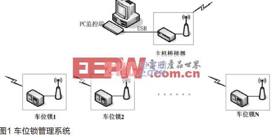
The whole system structure is shown in Figure 1. It consists of a host bridge and multiple intelligent parking lock nodes. It adopts a single-master multi-slave split structure. The network topology is determined by increasing or decreasing the number of parking lock terminals. Scalability and scalability.
Intelligent parking lock node
The intelligent parking lock node adopts the MCU+RF architecture, including the PSoC controller, communication module, motor control module, wireless transceiver module and power management module.
PSoC controller
PSoC is an 8-bit configurable embedded microcontroller from Cypress USA that provides a fast embedded mixed-signal solution. The biggest feature of PSoC is the integration of a large number of analog and digital resources and some additional practical system resources on a single chip. These resources are reconfigurable and dynamically reconfigurable and can be freely combined with their parameters. It can be selected or set to replace almost all common peripheral devices. This system adopts CY8C29466 with wide application and powerful functions. It integrates 8-bit M8C processor with 4MIPS performance, 32k bytes of Flash and 2k SRAM. It integrates 24/48MHz crystal oscillator, 32kHz crystal oscillator, and integrates 16 Programmable powerful digital subscriber modules, 12 analog subscriber modules and programmable internal interconnects make it easy to select up to 100 peripherals and set up connections for most PCBs (printed circuit boards) The components and traces are moved inside the chip and can be dynamically reconfigured for very flexible development.
Wireless communication module
The wireless communication module uses Cypress's RF chip CYRF6936, which belongs to the WirelessUSB LP series. It is Cypress's second-generation RF system-on-chip (SoC), which adds a series of enhanced features, including a wider operating voltage range (1.8~3.6V). , smaller operating current, higher data rate (maximum rate of 1Mbit/s), shorter crystal start-up time, synchronization stabilization time and link switching time.
Wireless transceiver module
The wireless transceiver module is divided into two parts: a wireless remote controller and a receiving module, which is used for realizing the opening and closing control of the user-level parking lock node, that is, sending a control signal to the receiver of the parking space lock through the control button on the wireless remote controller, and the receiver performs the control. After the signal is decoded, it is passed to the controller for processing, and the automatic opening and closing control of the parking lock is realized.
The wireless remote control uses a very wide 150m four-button remote control, which uses the PT2262 chip for encoding; the receiving module uses the PT2272 decoder chip, which has four outputs, corresponding to the four buttons on the remote control. If a button is pressed, the corresponding output is a logic high level, and when it is released, it is a low level.
Motor control module
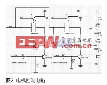
The motor control circuit is shown in Figure 2. CTRM+ and CTRM- are respectively connected to the two output pins of the MCU. When CTRM+ is "1", the transistor Q2 is turned on, and the relay K1 is energized to make the M+ (motor forward interface). Connected to the 6V power supply, the motor rotates forward, driving the parking arm to rise, preventing other vehicles from occupying the parking space; if CTRM- is "1", the transistor Q3 is turned on, and the relay K2 is energized to make the M- (motor reverse The interface is connected to the 6V power supply, the motor is reversed, and the parking arm is lowered to drive the car into the parking space.
Power management module
The power supply is provided by a 6V battery, while the MCU chip CY8C29466 requires a working voltage of 5V, and the communication chip CYRF6936 requires a working voltage of 3.3V. Therefore, the voltage of the 6V battery is converted by the voltage regulator chips L1117-5.0 and L1117-3.3. At the same time, the battery power is monitored in real time. When the battery capacity drops to a certain value, a charging demand signal is sent to the system, so that the staff can replace the battery in time.
Host bridge
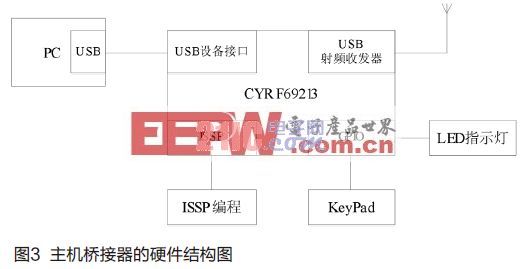
The host bridge is used to receive status information from the parking lock terminal and send it to the host computer via the USB protocol. The chip uses Cypress's PRoCTM LP chip CYRF69213, which integrates an 8-bit M8C processor with 4MIPS performance, USB2.0 low-speed interface, 2.4GHz RF transceiver, and internal 3.3V voltage regulator, which greatly reduces external components. Can effectively reduce costs and speed up the development process, the hardware structure is shown in Figure 3.
The hardware of the system consists of a host bridge and a parking lock node, mainly based on the PSoC and PRoC architectures. The hardware diagram of the system is shown in Figure 4.
System software design
The software design of this system revolves around the extraction, transmission and processing of data. Looking up from the data flow, the data is processed in three stages, namely WirelessUSB protocol processing, USB protocol processing, and PC monitoring software processing (displaying monitoring data). The system can be divided into three parts from the hardware: parking lock node, host bridge and PC. The parking lock is handled by the WirelessUSB protocol; the host bridge includes WirelessUSB protocol processing and USB protocol processing; and the PC includes USB protocol processing and monitoring software processing.
Parking lock node
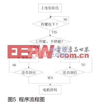
When the vehicle approaches the parking space, the owner presses the unlock button of the remote controller, and the receiving circuit decodes the received signal, and sends the decoding result to the single-chip microcomputer, and the single-chip computer analyzes and compares the received decoded signal. If the signal matches the already stored identity code in the memory, it means that it is a legitimate vehicle, and the single-chip microcomputer controls the motor to lower the parking space lock. After the position is lowered, an audible signal is emitted, and after the driver hears the sound, the vehicle is driven into the parking space, and When leaving, the parking lock is raised to prevent theft. The program flow chart is shown in Figure 4.
WirelessUSB network
The WirelessUSB wireless network is a master-multi-slave (point-to-multipoint) star network architecture that includes a host (bridge) and multiple slaves (up to 255 slaves) for bidirectional data transmission.
The WirelessUSB host is responsible for detecting interference, selecting a quiet channel, normally in receive mode, and sending acknowledgement data when the device polls. After the host is powered on, it enters the channel selection mode. After finding a quiet channel, it enters the data mode. When the user requests binding, it enters the binding mode, and when the binding ends, it will enter the channel selection mode. If the current channel's noise interference is too large, the host will re-enter the channel selection mode.
The WirelessUSB slave immediately sends data to the host (does not detect the channel idle), sleeps (power saves) when there is no data, and periodically polls the host for configuration data. After the power-on reset, check whether the device is bound. If it is bound, enter the reconnect mode. If it is not bound, it enters the idle mode and waits for the user to bind. When the user manually binds, it enters the binding mode. After the end, it will enter the reconnect mode. After the host is found, it will enter the data mode. In data mode, if the connection is lost, it will automatically enter reconnect mode.
PC monitoring terminal
The driver layer of the PC monitoring software mainly includes the driver of the USB interface; the protocol layer package
Figure 5 The program flow diagram includes the USB host protocol; the main work of the application layer further analyzes the processing data and processes user input. In order to speed up the development process and make full use of the existing resources, the host-side USB driver is not re-developed, and the CyDrive API is provided by Cypress. The CyUSB API provides a high-level application interface, which greatly facilitates the writing of applications. The upper computer monitoring interface is written by VC6.0 MFC, which displays the total number of parking spaces detected, the number of free parking spaces and the number of occupied vehicles, and lists all the details of the parking spaces and the current power of each parking lock.
Conclusion
The parking lock management system is a low-cost, high-performance management system that takes full advantage of PSoC's internal resources and the flexibility and freedom of WirelessUSB. The entire system includes two modules, PC software and embedded devices, supporting plug and play. The system communicates with the PC software through the USB2.0 interface, which is highly scalable and can collect up to 255 parking spaces at the same time. In addition, the system can upload the parking space information to the upper computer management software via WirelessUSB, and the upper computer management software displays the information occupied by the parking space. The operator can use this information to manage the entire parking lot, which is beneficial to improve the management order of the parking lot, reduce the labor intensity of management personnel, and reduce management costs.
- These lights look like many beautiful fire flies, and the copper wire is extra flexible, You can decorate teenager or girls 's rooms to enjoy ambience of relaxing, decorate your wedding to memorize your important and romantic moment, decorate it in restaurant or shop, create welcome feeling, customers will be attracted by the twinkle String Lights,walk into shop or restaurant, stay longer, enjoy their commodity or food and love your shop or restaurant.
- You can also decorate your party to feel more joyful, decorate holidays and Christmas to enjoy happy times.With extra flexible copper wire, you can put these led starry string lights in the glass jar,vase, or you can easily bend and shape it around wreaths, trees, flowers, and almost everything else.
Battery Led String Lights,Led String Lights,Outdoor String Lights,Solar Led String Lights
Dongguan Xingyong Indusrtial Co,Ltd , http://www.xingyongled.com