
Abstract: In recent years, this is the case when personal valuables such as notebooks are stolen. A low-power wireless anti-theft device based on acceleration sensor is designed. It is proposed to build the simplest wireless sensor network through only 2 nodes, transmit PC mobile information, notify the owner to react quickly and avoid the loss of the notebook. Through the hardware circuit design and software programming programming, the entire network is driven, and the expected alarm effect is achieved through experimental tests. The utility model solves the defects that the general anti-theft device is expensive, the system is complicated, the volume is large, and the delay is long.
With the continuous development of the social economy, the popularity of notebooks has become more and more popular, and the security and theft of PCs have become increasingly prominent. It is inconvenient to carry a notebook with you on some occasions. For example, when traveling by train, when the owner goes to the bathroom, how to prevent and prevent the thief from stealing the notebook at this time is an urgent problem to be solved. Today's widely used car anti-theft technology is very mature, but relatively high cost, and no need to consider power problems, and PC anti-theft must solve these problems; also small size, can be installed on the PC at any time. Here, it is proposed to use only two nodes based on the Simplici TI communication protocol (with accelerometer) for point-to-point communication to complete the anti-theft function.
1 overall plan
The system design is very simple. Generally speaking, the total length of the train carriage is 26.6 m, and the communication distance of the wireless sensor net2works (WSN) is between tens of meters and several hundred meters, generally 30 m, so that one node can completely cover the entire compartment. There are only 2 nodes in the system (without PC assistance): Node 1 acts as the sender and Node 2 acts as the receiver, making up the simplest network without jumping. The structure of the system is simple, so that the transmission delay is very small, and it is suitable for the application mentioned above.
1.1 Program implementation
The train compartment is divided into two zones: Zone 1 is the location of the PC, that is, the seat of the owner. When the person does not leave, Zone 1 is safe; Zone 2 is the rest of the compartment where Zone 1 is removed. When the owner enters Zone 2 due to a problem, Zone 1 will become a blind spot and the PC will become unsafe. The solution implementation steps are shown in Figure 1.
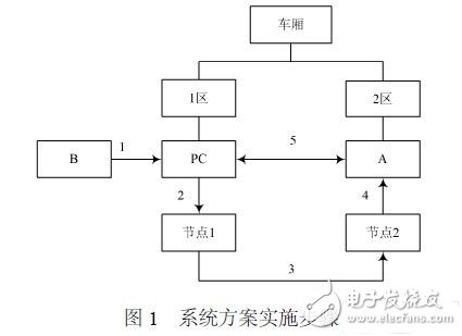
Implementation steps:
(1) Thief B attempts to move the computer;
(2) The movement of the computer causes the node 1 fixed above to move;
(3) The acceleration sensor on node 1 acquires the speed information, and the RF chip on node 1 transmits the speed information;
(4) Node 2 receives the information, determines whether the speed PC belongs to the abnormal movement by a predetermined program, and if so, triggers the buzzer to alarm, and vice versa;
(5) Master A quickly returns to his seat after hearing the alarm to avoid PC loss.
1.2 Anti-theft device principle
Strictly speaking, the system has only 2 nodes: Node 1 (fixed) is a wireless sensor module with acceleration sensor for collecting and processing speed information, and then the RF chip sends the information; node 2 (mobile) is a A wireless sensing module with a buzzer is used to determine whether the speed information sent by the node 1 exceeds a predetermined threshold to determine whether to trigger the buzzer to alarm.
Ideally, the train will have zero acceleration at constant speed, but there will be a certain three-dimensional acceleration in the case of turning, changing rails, etc. Let the train advance direction be the x-axis, the left side of the forward direction be the y-axis, and the upper side be the z-axis. Considering that the car body is long and the rails are more equal, and according to experience, in the case of normal turning, changing rails, etc., the car body mainly swayes left and right and accelerates back and forth, with little vibration. If the x-axis acceleration is ax, the y-axis acceleration is ay, and the z-axis acceleration is az, then ax, ay are both greater than zero, and az is close to zero. When the PC is stationary relative to the train, if the thief wants to move it, it will inevitably cause acceleration on the 3 axes, so that the acceleration caused by the vehicle body sway will be superimposed with the acceleration caused by the human movement, and the interference judgment will impose an additional computational burden on the system. According to this, az can be selected as the judgment object for judging whether the notebook is moving or not, because in general, az is considered to be the acceleration caused by human movement.
Although the az caused by the vibration of the car body can be approximately zero, it may not be zero in some special cases. In order to reduce the false alarm rate, the system sets a certain buffer value, so that the anti-theft device can accommodate some body vibration. However, in order to recognize the artificial movement, the buffer value cannot exceed the acceleration caused by the artificial movement, which is the judgment threshold of the system.
Now take the data from a simple experiment to calculate the az caused by human movement: pick up the notebook at random, repeat 10 times, record the time used for a short distance of 10 cm). The 10 sets of data are shown in Table 1.
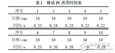
Using the data in the table, the average time (unit: s) can be calculated as: t = (0.25 + 0.24 + 0.23 + 0.22 + 0.22 + 0.23 + 0.20 + 0.28 + 0.30 + 0.28) â„10 = 0.245 displacement formula is given by equation (1) :

Where: s , v0 , a are vectors on the z-axis. According to the previous analysis, s = 10 cm; v0 = 0 mâ„s; t = 0.245 s. According to formula (1), a ≈3.332 mâ„s2 can be calculated, which is about 0.340 g, which is az. In order to reduce the false positive rate and maximize the recognition of artificial mobile PCs, the threshold compromise is set to 0.20 g.
2 hardware implementation
The system has only 2 nodes, so the network construction is simple and rapid, and the article first puts forward the concept of “use and buildâ€.
2.1 node design
The system uses Chipcon's single-chip, multi-band, low-power, ultra-high frequency RF chip CC1010. The chip is fabricated in 0.35 μm CMOS technology with a high-performance 8051 microcontroller, 33-channel 10-bit ADC, 4 timers, 2 PWMs, 2 UARTs, SPI, and 26 general-purpose I/Os.
2.1.1 Design of RF Transceiver Circuit Between CC1010 and Antenna
The circuit of the RF transceiver part is shown in Figure 2.
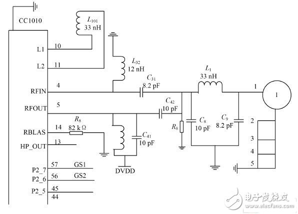
Figure 2 Circuit of the RF transceiver part
In the figure, C31 is the input matching capacitor, L32 is the input matching inductor, and L32 is also used to prevent the input of the DC bias signal; C41, C42 and L41 together achieve the matching of the transmit output circuit. The transceiver's internal transmit/receive switch circuit allows the transceiver to transmit and receive through the same 50 Ω antenna. L1, C8, and C9 form a low-pass filter that filters out high-frequency harmonics and increases frequency selectivity with an impedance of 50 Ω. Component parameters can be obtained either by the values ​​given on the CC1010datasheet or by Chipcon's SmartRF Studio software.
2.1.2 Interface Circuit Design of CC1010 and Acceleration Sensor
This wireless acquisition system uses the latest low-cost, single-chip, three-axis acceleration sensor MMA7260 from Freescale. The miniature capacitive acceleration sensor combines signal conditioning, single-pole low-pass filters, and temperature compensation to provide four acceleration measurement ranges of ±1.5 g, ±2 g, ±4 g, and ±6 g. Considering that the threshold is set to 0.2 g as before, the setting parameter sets the measurement range to ±1.5 g. In the interface between the CC1010 and the MMA7260, the noise problem must first be considered. Because the MMA7260 uses a switched-capacitor filter inside, and there is clock noise, it is necessary to connect the RC filter to the three outputs of XOU T, YOU T and ZOU T of MMA7260. Secondly, consider the voltage matching problem, because x , y , The voltage output in the z-axis direction is 0.45 to 2.85 V, and the maximum input range of the ADC of the CC1010 is 0 to V DD . Here, V DD = 3.3 V, which is well within the input range of the ADC, so there is no need to consider additional voltage divider resistors. The interface circuit of CC1010 and MMA7260 is shown in Figure 3. R31 â„C31, R41 â„C41, R51 â„C51 are used to filter out the switching noise of the MMA7260 internal sampling, and GS1 and GS2 are used for range selection.
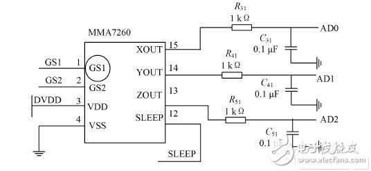
Figure 3 Interface circuit between CC1010 and acceleration sensor
2.2 Device Construction
Define the node 1 startup mode as the event trigger mode, that is, the node is often in the low power sleep mode. When the node has a certain movement in the z axis, the acceleration sensor can collect the acceleration information, and then notify the microcontroller to activate the node as the transmission mode. When the node is stationary, that is, when the acceleration sensor acquires an acceleration of 0, the node automatically enters sleep mode to reduce power consumption and fix node 1 to the PC before the owner leaves the seat.
According to the survey, the owner will not leave the computer on the train for too long, so the system sets node 2 (the buzzer on the LED light) to the receiving mode. The board burns a judgment program: the acceleration is caused by the train shaking. The collection and comprehensive analysis sets a certain threshold, and the threshold is greater than the acceleration caused by the train sway less than the acceleration caused by the abnormal movement. Carry node 2 with you, as long as the notebook moves abnormally, it will alarm. Since there are only 2 nodes, the system can quickly establish communication; and the node size is 37.67 mm &TImes; 25.80 mm, suitable for small space applications in the car.
By modifying the C language source code and transform sensor module (through the expansion slot) anytime and anywhere, you can also set up other functions wireless communication network: you can use the No. 1 board to monitor the temperature sensor changes, and the No. 2 board to monitor the temperature changes remotely; you can increase the wireless The gusset board builds a more complex multi-node wireless sensor network (Simplici TI single network can support up to 255 nodes). In summary, you can define “follow-to-use†as follows: Through a few simple wireless node boards and basic configuration PCs, a WSN based on Simplici TI communication protocol can be quickly set up anytime and anywhere to realize information collection, processing and transmission. Features. It can accommodate up to 256 nodes (including gateways) and can be modified at any time to implement multiple functions. This is convenient and maximizes cost and power savings. After completing the task, the node automatically goes into sleep mode, reclaims the node, and presses the button to power off the node.
3 test results and analysis
By testing the performance of the price alarm from several aspects such as delay, power consumption and false alarm rate.
(1) Delay. In order to save energy, the node is in sleep mode after the node is powered on. After a large number of laboratory tests, the delay from node to sleep activation is 15 ms, the device search delay is generally 30 ms, the active device channel access delay is 15 ms, and the ideal delay is 60 ms, but considering The electromagnetic environment in the compartment is complex, affecting many transmission factors, and the delay is set to 0.1 s.
(2) Power consumption. Based on the 433 MHz frequency, all pins operate at 14.8 mA in normal operation mode, 0.2 μA in sleep mode, and 29.4 μA in power-saving mode. Most of the time of the whole system is in the sleep energy-saving mode. If the PC is moved, the microcontroller of the node is woken up again by the event trigger mechanism. Once the system enters the energy-saving mode, the power supply circuit will cut off the power supply of the device except the one-chip computer, the RF module and the hardware watchdog. At this time, only the hardware watchdog, the serial port interrupt logic of the MCU and the RF module consume power, which can be the largest. Limit energy savings.
(3) False positive rate. The false positive rate is the most complicated and difficult problem to solve. Here, it is proposed to use the decision procedure, calculate the threshold, determine whether to exceed the threshold to determine whether to alarm, and greatly reduce the false positive rate while avoiding false negatives as much as possible.
4 Conclusion
Wireless sensor networks are considered one of the most important technologies of the 21st century. Here, based on WSN, focusing on solving the anti-theft problem of valuable items such as notebooks, a micro-powered notebook anti-theft device is designed. The innovation of the article is:
(1) A statistical method is used to determine a threshold by analyzing the x, y, z axis acceleration data caused by a large number of train sloshing and the acceleration data caused by the general human mobile PC. The threshold is greater than the normal shaking acceleration of the train; less than the artificial moving acceleration. Use the threshold to write a decision procedure to determine whether the notebook is alarming for abnormal movement.
(2) Put forward the concept of “use-and-useâ€, which enables the network to be quickly set up anytime and anywhere, greatly expanding the application of the anti-theft device; using the event trigger mode to activate the node, greatly reducing the power consumption of the node and the system.
Energy saving: LED lamp can save energy consumption cost of more than 70%.
Soft: flexible light strip can be bent to a minimum of 5 cm, and can be cut, so it must be bent into various text, graphics.
Color available : 12 single colors + RGB + digital. Please check our color card for effect.
This flex LED custom neon sign could be installed on all or hanging. It comes with hanging chain and hole in backing. You could customize any text, logo, colors and sizes as you wished. The neon sign will be a amazing decoration in your room, bar, shop or wedding etc. Please try Baiyang custom neon sign! Contact us before you order!
Power cord: 200cm(transparent)
Transformer 100V - 240V input for worldwide use, DC 12V output.
100% Handcrafted flex LED neon sign light.
Arrive safe warranty
Indoor use (Custom for outdoor usage)
1 year warranty
Package include: Neon Sign x 1, 110-240 Volt Transformers x 1, accessories for installation.
All of our neon signs supported customize. You could change colors, size and backing as you like. Just contact us!
Neon Sign Design,Directional Neon Signs,Trendy Neon Signs,Awesome Neon Signs
Shenzhen Oleda Technology Co.,Ltd , https://www.baiyangsign.com