
Author: Mentor Electronics (Mentor Graphics CorporaTIon) mechanical analysis, Dr. Erich Buergel, general manager,
Nowadays, the cost of electronic products accounts for about 30-40% of the total vehicle cost, and this number is steadily rising. These electronic products include not only functional components, such as engine control units, brake systems and transmission control devices, but also entertainment and navigation components. The explosive growth in the use of LED technology has recently demonstrated this point. For example, all new cars in Europe must be equipped with daytime running lights, and LEDs have become the preferred lighting technology because of their low power consumption and high efficiency.
Efficient thermal management is very important, because the LED will continue to emit heat, and the LED lamp cover is getting smaller and smaller. With the continuous improvement of brightness and power, LEDs (such as car head and tail lights) that are closely arranged cannot be cooled by fans. Therefore, reliability and performance are bound to be affected. When the LED exceeds the critical junction temperature, two problems arise. First, the LED will dim and the color will change. Secondly, if the temperature continues to be too high, their service life will be shortened, and then scrapped prematurely. The average lifespan of automotive LEDs is several thousand hours. These problems will bring additional warranty costs for manufacturers.
Good thermal design is critical to efficient thermal management. LED components are the first link in the design process (see Figure 1). Component designers use thermal analysis software and measurement hardware to analyze the material and structure of the component to ensure that the heat generated by the junction can be easily dissipated through the LED layers. The subsystem designer will arrange the LEDs in an array, add radiators and other cooling devices, and then analyze the product again. They may adjust the separation distance between the LEDs or add additional cooling devices to ensure that the LEDs do not exceed the critical temperature. The final step is usually completed by a mechanical designer using a mechanical computer-aided design (MCAD) system. The designer will put the aligned LED lights into the lampshade (such as a car headlight), while using advanced computational fluid dynamics (CFD) ) The software performs thermal analysis.
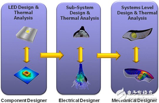
Figure 1: Thermal analysis at all stages of LED design is necessary for good thermal management.
If the problem of thermal management at the component level is solved, it does not mean that the problem of the subsystem is also solved. Solving the thermal management problem of the subsystem does not mean that the thermal management problem of the system is solved. Only by solving all thermal problems can we ensure that this design has good thermal management.
Design gap
Excellent CFD thermal analysis software has been available for many years. Products such as FloTHERM are fast and accurate, and their ease of use is ideal for designers. But the quality of this analysis depends on the thermal model of the components provided to the software. No matter how good the analysis is, inaccurate patterns will only mislead you.
The typical LED data sheet provided by the supplier will only show a lot of power loss (such as maximum forward current and voltage) and a single thermal resistance between the junction and some references, such as solder joints. There is no information on how the heat passes through the layers and radiates. There is also no thermal path / barrier description that can be used to define the thermal resistance and capacitance of each layer.
Therefore, thermal experts usually estimate the internal structure of the device and create a thermal model to illustrate the thermal resistance and capacitance of each layer and each structure. But thermal experts only need a few percentage points of deviation to cause inaccurate analysis. There is no way to verify or judge the accuracy of the thermal model when using this method.
Therefore, there are gaps in the process of excellent thermal design. In all aspects of product development (components, subsystems and the entire system), thermal analysis is absolutely indispensable. However, the thermal analysis results can only be considered good if the component thermal model is good. Without understanding the internal structure of the component, we cannot define or verify the accuracy of the model, and usually component suppliers will not disclose intellectual property in this regard.
Fill the gap
The solution to this problem is to simplify the thermal model by defining and verifying components as shown in Figure 2, and establish a connection between hardware test / measurement and thermal analysis. Existing hardware can measure the thermal characteristics of a component. For example, the T3Ster hardware of Bright Conductor is attached to electronic components such as LEDs to measure the transient junction temperature. Whether the component is powered or not, it can be accurate to 0.01 degrees Celsius. In the process of heat dissipation from the node to the surrounding environment, the transient temperature characteristic map can collect more than 10,000 data points in one minute, which is used to describe the thermal resistance and capacitance of the element layer.
With these data, the software can automatically generate LED simplified thermal patterns. Engineers can now have a precise and effective model.
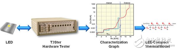
Figure 2: Hardware test and measurement can be used to create or verify a simplified thermal pattern for LEDs.
The ability to create accurate and effective thermal models of components has effectively filled the gaps in the thermal management design process. This brings many benefits to the electronics industry. LED suppliers can use this technique to test thermal characteristics during the design process and generate thermally optimized designs before testing and creating a thermal model for customers. Subsystems and system developers can use it to verify models obtained from suppliers or to create models themselves if the suppliers do not provide them. Original equipment manufacturers are affected by critical reliability electronics, because quality assurance and recycling issues directly affect their profit and loss. They need 100% trust in their product design.
Office Window Cleaning Robot apply to office, home, hotel, shop and so on. You can saves the labor, money, energy using smart window robot clean office. Office window robot is suitable for frame glass (rimless glass is also ok), door, wall. The noise is only 48dB when you use window robot clean office, giving you a quite environment.
Window Cleaning Robot Reviews beat HOBOT window robot, we become to Top sale . window cleaning robot test very good before leaving facotry. Welcome to place order ws - 960 window cleaning robot.

Specifications of robotic window cleaner:
Dimensions: 285*136*100mm
Weight: 0.92kg
Cleaning speed: 3′/㎡
Applicable Area: ≤100㎡
Working height: No limited
Anti-drop control: UPS / safety rope
Detection window frame: Auto recognition
Operation: Automatic / remote control
Alarm prompt function: Voice alarm
If there is anything confusing you, please feel free to contact me for further discussion. Our factory is in Shenzhen, China. Welcome to visit. It will be our honor to see you.
Office Window Cleaning Robot
Office Window Cleaning Robot,Building Window Cleaning Robot,Window Cleaning Robot Reviews,Office Building Window Cleaning Robot,Window Cleaning Robot Reviews,Window Cleaning Robot For Office
Zhengzhou Bangmi Smart Technology Co., Ltd. , https://www.cleanwindow-robot.com