
Automatic vehicle shifting is an important part of automotive electronic control technology. The use of computer and power electronic drive technology to achieve automatic vehicle shifting can eliminate the difference in driver shifting technology, reduce the driver's labor intensity, improve driving safety, and improve vehicle power and economy. The continuously variable transmission system of a car is generally composed of a continuously variable transmission (CVT) and a transmission control unit (TCU).
This article refers to the address: http://
1 Basic structure of CVT
The infinitely variable transmission system of the automobile mainly has the following forms: (1) Hydrodynamic Mechanical Transmission (HMT) is widely used in cars, buses, heavy vehicles, commercial vehicles and construction vehicles. (2) Mechanical AT-AMT (Automatic Mechanical Transmission) is based on the general mechanical transmission and is equipped with a microcomputer-controlled electro-hydraulic servo-operated automatic shifting mechanism. It is currently used in some low-end cars, local trucks and commercial vehicles. (3) Continuously Variable Transmission (AT-CVT) is currently the most used in small-displacement cars. Its main structure and working principle are shown in Figure 1.
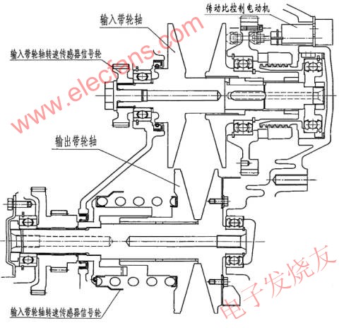
Figure 1 The main structure and working principle of the stepless AT-CVT
The development of CVT technology has a history of more than 100 years. Germany's Mercedes-Benz is the originator of CVT technology in automobiles. As early as 1886, the V-type rubber belt CVT was installed on the gasoline engine car produced by the company. However, due to problems in structural design and material selection, the transmission mechanism is too large and the transmission ratio is too small to meet the requirements of the vehicle. These shortcomings limit its application. Until 1979, through the improvement of the structure and the use of special steel belts, the transmission ratio of CVT was significantly improved, and it has the preconditions for wide application in vehicles. Since then, shifting transmissions have been used in models from companies such as Ford, Fiat and Nissan.
The V-shaped thrust steel strip used in the CVT consists of a plurality of wedge-shaped steel sheets mounted on a flexible maraging steel ring. Its power is input from the drive wheel, through the V-shaped steel belt, and output from the driven wheel. The pulley is composed of two parts that can slide relative to each other. The steel strip is located in the groove between the two parts. When the two parts of the pulley are tight, the groove is narrow, and the steel belt is located at the outer edge of the pulley, and the working diameter of the pulley is the largest at this time. With the relative sliding between the two parts, the groove becomes wider and wider, and the steel strip gradually approaches the center of the pulley, that is, the place where the working diameter is the smallest. When the vehicle has just started to drive at a lower speed, the driving wheel has a smaller working diameter, and the transmission can obtain a larger transmission ratio, so that the vehicle obtains sufficient power to overcome the running resistance. As the vehicle speed increases, the working wheel diameter gradually increases, the working diameter of the driven wheel becomes smaller and smaller, and the transmission ratio is also reduced accordingly. Since the working diameter of the pulley can be continuously changed, the transmission ratio of the transmission is also stepless, continuously changing, and the transmission power is more stable, and its power and economy are much higher than that of the planetary gear type automatic transmission. The control of the transmission ratio of the car in actual operation is automatically completed by the TCU controlling the DC motor.
2 basic structure of TCU
The basic structure of the TCU is shown in Figure 2. It consists of a microcontroller, a detection circuit, a drive circuit, a power supply circuit, and a communication circuit.
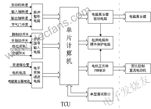
Figure 2 The basic structure of the TCU
The single-chip microcomputer adopts the single-chip PIC18F452 which was introduced by Microchip in the United States in March 2002. It can meet the requirements of TCU in function. It has low power consumption, wide operating temperature range and can work normally at lower voltage. Especially suitable for automotive electrical appliances. The detection circuit is divided into pulse detection, switching quantity detection and analog quantity detection. Pulse detection is further divided into pulse count and pulse width detection. For example, the measurement of the starting speed, input and output shaft speed is pulse counting. The throttle opening is measured by pulse width measurement.
The analog measurement is mainly composed of a filter circuit and an amplifier circuit. The A/D conversion is a 10-bit A/D converter that comes with the microcontroller. The ratio control of the gearbox is driven by a DC motor. In the TCU, an H-type circuit composed of four MOSFETs implements positive and negative PWM control of the motor. The current of the electromagnetic clutch is also driven by the MOSFET. In addition to the main switching element and the freewheeling diode, there are a protection circuit and a current detecting circuit in the driving circuit.
The role of the communication interface is mainly to observe the working state of the TCU, the failure analysis of the detection sensor and the sharing of sensor resources.
3 TCU control system block diagram
The main block diagram of the TCU control system is shown in Figure 3. The program first allocates the internal RAM and then initializes each function module such as the Administrator/D converter, timer, PWM waveform generator, and so on. The ratio of the gearbox should be at the minimum ratio of the car at each time. Therefore, the gearbox should be reset every time it stops. After the car starts, the parameters are first detected, such as the gear switch, engine speed, and throttle opening. Degree, gearbox input, output shaft speed, etc. These parameters are the basis for controlling the electromagnetic clutch current and motor state. When it is necessary to increase the ratio of the gearbox, the TCU controls the motor to rotate forward, and vice versa. The electromagnetic clutch is controlled by current increment control. Its control is good or bad, which directly affects the stability and economy of the car operation.
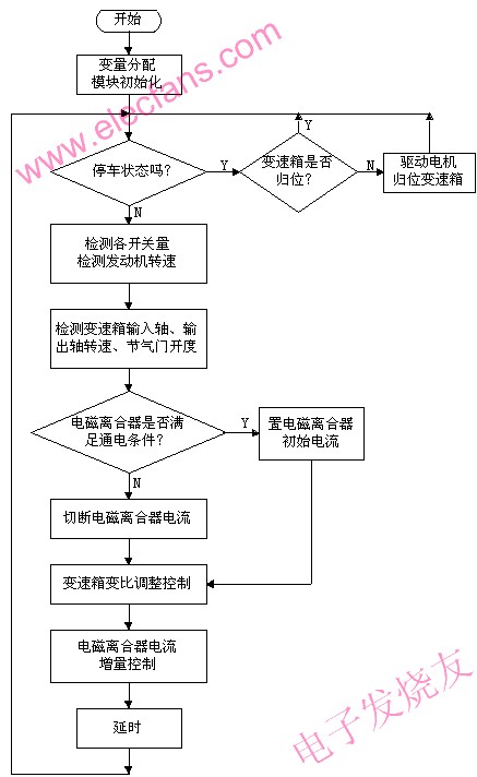
Figure 3 TCU control system main block diagram
4 results
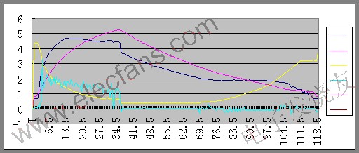
Figure 4 and Figure 5 show the relationship between the electromagnetic clutch current and the gearbox ratio during actual vehicle operation. Figure 4 is a graph of the electromagnetic clutch current and engine speed, throttle opening and input shaft speed when the vehicle speed is accelerated from zero to 120KM/H to 120KM/H and the throttle is decelerated to zero. It can be seen from the figure that the throttle valve is added to the maximum and remains for a period of time. The electromagnetic clutch current is synchronously followed by the addition. When added to the peak, it continues to remain unchanged, and the engine speed is also added to a value that remains unchanged. It can also be seen that the electromagnetic clutch current is constantly shaking during the process of increasing. It can be seen that the electromagnetic clutch is continuously slipping during the ascent. During this time, the engine speed is not proportional to the input shaft speed until the electromagnetic clutch reaches a stable state. Only after the value is maintained a certain proportional relationship. When the throttle is fully released, the electromagnetic clutch current drops to a small value and remains unchanged until the vehicle speed reaches the gearbox being shifted by the gear. The electromagnetic clutch current continues to decrease. When the vehicle speed is zero, The electromagnetic clutch current is then reduced to zero. As can be seen from Fig. 4, when the vehicle speed is increased from zero to 120 KM/H, the electromagnetic clutch current is zero, and the input shaft speed is gradually reduced to zero. Throughout the process, we can see that the rate of change of the throttle opening represents the driver's intention, and the electromagnetic clutch current is mainly determined by the throttle opening. The degree of slip of the electromagnetic clutch determines the proportional relationship between the engine speed and the input shaft speed.
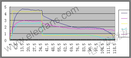
Note: dark blue - input shaft speed, yellow - throttle opening, purple - engine speed, light blue - electromagnetic clutch current
Figure 4 Electromagnetic clutch current curve when the motor is accelerating
Figure 5 is the relationship between the position sensor and the input shaft speed, output shaft speed and motor voltage when the vehicle speed is increased from zero to 120KM/H and then reduced from 120KM/H to zero. As can be seen from the figure, when the car speed is increased from zero to 120KM/H, the position sensor ratio is reduced from the maximum to the minimum, and the corresponding motor is reversed. When the vehicle speed starts to decrease from 120KM/H, the position sensor will remain unchanged first. At this time, the motor will not rotate, and the input shaft speed will decrease proportionally to the output speed. When the vehicle speed reaches a certain value, the position sensor speed ratio will be increased from the minimum until the vehicle speed reaches a certain value. For the maximum value, the motor is reversed at this time (the current sensor used in the test is unidirectional, so the reverse current is not reflected in the figure). The input shaft speed and the output shaft speed are disproportionately reduced to zero. It can be seen from Fig. 5 that the test value of the position sensor speed ratio is continuously decreasing when the vehicle speed is rising (the corresponding speed ratio is increased). Conversely, when the vehicle speed is decreasing, the test value increases when the vehicle speed is less than a certain value. Thereby automatic adjustment of the gearbox ratio is achieved.
Note: yellow - position sensor, dark blue - input shaft speed, purple red - output shaft speed, light blue - motor voltage
Figure 5 Gearbox ratio when the car is decelerating - speed curve
It can be seen from the running results that the designed TCU can realize the automatic control of the electromagnetic clutch torque and the gearbox ratio. From the actual operating feeling, the start and stop and the acceleration and deceleration process are smooth. And it has good economy.
The Description of Gsm Magnetic Antenna
GSM Magnetic Antenna Features :
Vehicle exterior antenna. Multi-band versatility.
Easy to install and use.
Lightweight and weatherproof.
Good quality. Keep it in place while traveling.
Simply transfer from one car to another.
More signal for your phone when you are driving.

The Specifications of GSM Magnetic Antenna
* Frequency range: 900-1800MHz.
* Bandwidth: 70/170MHz.
* Gain: 3 -5dBi.
* VSWR: ≤2.0.
* Input Impedance: 50Ω
* Maximum input power: 50W
*Wire length: 3M/Customized
* Input connector type: SMA Male/Customized.
*Operating temperature: -40~60ºC
*Polarization: Vertical
*Mounting way: Magnetic adsorption
GSM Magnetic Antenna
Gsm Magnetic Antenna,Magnetic Base Antenna,GSM Magnetic Base Antenna,Magnetic Car Antenna
Shenzhen Yetnorson Technology Co., Ltd. , http://www.yetnorson.com