As far as the current domestic LED driver power supply design trend is concerned, the product that uses the capacitor buck principle to complete the drive circuit design has gradually established itself in the market. LED power products with this design have better stability and lower cost. In today's article, we will briefly analyze and introduce the principle of capacitor buck in LED driver power.
The block diagram of the buck principle in the LED drive power circuit fabricated using the capacitor buck principle is shown in the figure below. When a sinusoidal AC power source U (herein the most common 220VAC, 50HZ is used as an example) is applied to the capacitor circuit, the charge on the plates of the capacitor and the electric field between the plates are a function of time. That is to say: the effective value and amplitude of the voltage and current on the capacitor also follow Ohm's law. That is, the amplitude of the voltage applied to the capacitor is constant, and when the frequency is constant, a stable sinusoidal alternating current ic flows. The smaller the capacitive reactance, the larger the capacitance value, the larger the current flowing through the capacitor, and a suitable load in series with the capacitor, a reduced voltage source can be obtained, which can be rectified, filtered, and regulated. One problem to be noted here is that in this circuit system, the capacitance is only the throughput energy in the circuit, and does not consume energy, so the efficiency of the capacitance step-down circuit is high.

LED drive power capacitor step-down block diagram
Under normal circumstances, the LED power supply designed by the capacitor buck principle, its main drive circuit will be composed of buck capacitor, current limiting, rectification filtering and voltage regulation shunt. Among them, the step-down capacitor is equivalent to the step-down transformer in the ordinary voltage regulator circuit, directly connected to the AC power circuit, almost all AC power supply U, should use non-polar metal film capacitor. At the moment of closing the power supply, there may be a peak-to-peak value of the positive or negative half of U. At this time, the instantaneous current will be large. Therefore, a current limiting resistor must be connected in series in the loop to ensure the safety of the circuit. The main reason for the circuit is essential. The design requirements of the rectifier filter circuit part are the same as those of the ordinary DC stabilized power supply circuit. The reason why the voltage shunt circuit is needed is because the voltage RMS is stable and is not affected by the change of the load current. Therefore, in the voltage regulator circuit, there must be a shunt circuit in response to the load. The magnitude of the current changes.
PCB Material Fr4 Substrate PCB Board Manufacturing Service
As you know, the Printed Circuit Board plays a vital role in electronic products, so you need to consider how to choose the right material in your PCB Manufacturing. JHYPCB can offer you the lowest possible costs and the very finest in high-quality PCB fabrication and high-quality PCB Assembly . However, there are many different types of PCB materials, such as FR-4 material, HDI material, Rogers PCB material, and so on. In general, we use the standard FR-4 material for the Printed Circuit Boards to reduce product costs, which is a good option because FR-4 material is affordable and useful for many applications. However, FR-4 material is not the only type of PCB material; comparing to PCB material, FR-4 material, and Rogers material is essential.


What is FR4?
FR4 is a standard defined by the NEMA (National Electrical Manufacturers Association) for a glass-reinforced epoxy resin laminate.
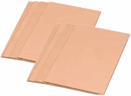
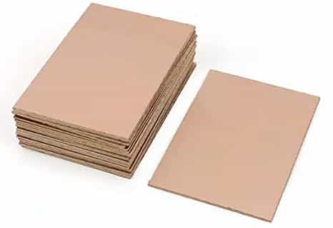
"FR" indicates the material is flame-retardant, and the "4" indicates woven glass-reinforced epoxy resin. Single or double-sided PCB structures consist of an FR4 core and top and bottom copper layers. Multilayer PCB boards have additional prepreg layers between the center core and top and bottom copper layers. The core consists of a substrate with copper covering, also referred to as a copper-clad laminate(CCL). The core, laminate, and prepreg may all be FR4 with the copper sheets between the signal and ground layers. FR4 is the most common material grade that comprises fabricated circuit boards.
FR-4 or FR4`s properties and characteristics make it very versatile at an affordable cost. Before the explosion of multilayer PCBs, there were many alternative board materials to FR4. These included FR2, CEM 1, and CEM 3, which were paper-based. However, the strength of FR4, especially for multilayer PCB boards, was a significant factor in separating it from alternatives to become the industry standard. Therefore, Most PCBs are made using FR4 as the base material.
FR4 materials and characteristics
Its glass transition (TG) is 115°C to 200°C for the High TGs or HiTGs, depending on the manufacturing methods and the resins used. A standard FR-4 PCB will have a layer of FR-4 sandwiched between two thin layers of laminated copper.
FR-4 uses bromine, a so-called halogen chemical element that is fire resistant. It replaced G-10, another less resistant composite, in most of its applications.
FR4 has the advantage of having an excellent resistance-weight ratio. It does not absorb water, keeps high mechanical strength, and has an excellent insulating capacity in dry or humid environments.
Examples of FR-4
- Standard FR4: as its name indicates, this is the standard FR-4 with heat resistance of the order of 140°C to 150°C.
- High TG FR4: this type of FR-4 has higher glass transition (TG) of around 180°C.
- High CTI FR4: Comparative Tracking Index higher than 600 Volts.
- FR4 with no laminated copper: ideal for insulation plates and board supports.
- There are more details of the characteristics of these different materials later in the article.
Factors to consider when choosing the thickness
- Compatibility with components: even though FR-4 is used to produce many types of the printed circuit, its thickness affects its components. For example, THT components are different from other components and require a thin PCB.
- Space-saving: space saving is essential when designing a PCB, particularly for USB connectors and Bluetooth accessories. The thinnest boards are used in configurations in which space-saving is crucial.
- Design and flexibility: most manufacturers prefer thick boards to thin ones. Using FR-4, if the substrate is too thin, it would be at risk of breaking if the board dimensions were increased. On the other hand, thicker boards are flexible and make it possible to create V-grooves.
- The environment in the PCB that will be used must be considered. For an electronic control unit in the medical field, thin PCBs guarantee reduced stress. Boards that are too thin - and therefore too flexible - are more vulnerable to heat. They can bend and take on an undesirable angle during the component soldering steps.
- Impedance control: the board thickness implies the dielectric environment consistency, in this case, FR-4, which facilitates impedance control. When impedance is an essential factor, the board thickness is a determining criterion to be taken into account.
- Connections: the type of connectors used for a printed circuit also determines the FR-4 thickness.
The Different Types of FR-4 Available From JHYPCB
JHYPCB STANDARD FR-4 MATERIAL PROPERTIES
- High Glass Transition Temperature (Tg) (150Tg or 170Tg)
- High Decomposition Temperature (Td) (> 345º C)
- Low Coefficient of Thermal Expansion (CTE) ((2.5%-3.8%)
- Dielectric Constant (@1 GHz): 4.25-4.55
- Dissipation Factor (@ 1 GHz): 0.016
- UL rated (94V-0, CTI = 3 minimum)
- Compatible with standard and lead-free assembly.
- Laminate thickness available from 0.005" to 0.125"
- Pre-preg thicknesses available (approximate after lamination):
- (1080 glass style) 0.0022"
- (2116 glass style) 0.0042"
- (7628 glass style) 0.0075"
Standard FR4
- FR4 SHENGYI family S1000H
- Thickness from 0.2 to 3.2 mm.
- FR4 VENTEC family VT 481
- Thickness from 0.2 to 3.2 mm.
FR4 High TG
- FR4 SHENGYI family S1000-2
- Thickness from 0.6 to 3.2 mm.
- FR4 VENTEC family VT 47
- Thickness from 0.6 to 3.2 mm.
FR4 High IRC
- FR4 SHENGYI family S1600
- Standard thickness 1.6 mm.
- FR4 VENTEC family VT 42C
- Standard thickness 1.6 mm.
FR4 with no copper
- This material is an epoxy glass with no copper, designed for use in insulation plates, templates, board supports, etc. They are manufactured using Gerber type mechanical drawings or DXF files.
- Thickness from 0.3 to 5 mm.
The Difference Between FR-4 Material and Rogers Material
1. FR-4 material is cheaper than Rogers material.
2. Comparing to FR-4 material, Rogers material is great with high frequencies.
3. FR-4 material has a high Df or dissipation factor than Rogers material, suffering more signal loss.
4. In impedance stability, Rogers material has a wider range of Dk values than FR-4 material.
5. For dielectric constant, FR-4 features a Dk of about 4.5, which is lower than Rogers material with around 6.15 to 11.
6. In temperature management, Rogers material has a less variation comparing to FR-4 material.
When is FR4 Not the Best Material For Your Board?
FR4 is indeed a good standard or default option for your board material in most cases. However, there are cases where FR4 is not the best material for your board, as listed below.
- If lead-free soldering is required
If your boards will be distributed in Europe and must adhere to The Restriction of Hazardous Substances Directive (RoHS) or your client necessitates that lead-free soldering be used, then you may want to explore other material options. This is due to the fact that reflow temperatures for no-lead PCBA(Lead-free PCB Assembly) may reach as high as 250°C, which substantially exceeds the Tg for many versions of FR4.
- If high-frequency signals are used
At high frequencies, FR4 boards are not able to maintain a constant impedance and reflections may occur that negatively impact signal integrity. This is a consequence of the relatively high value for dk.
- If the board will be exposed to extremely high temperatures during operation
It is also ill-advised to use FR4 if the PCB will be required to operate in an environment under extremely high temperatures. An example would be near the engine compartment of an aerospace vehicle.
FR4 is rightly the most used material in PCB construction. Boards made from FR4 are strong, water resistant, and provide good insulation between copper layers that minimizes interference and supports good signal integrity. However, at high frequencies and in environments, FR4 is not the best material to use for your boards. At JHYPCB, the industry leader in fast, high-quality PCB Prototype and low-volume manufacturing, we are capable to meet your board material needs for any case. We will work with you to help you select the materials that will best implement your design intent.
And to help you get started on the best path, we furnish information for your DFM checks. If you are ready to have your design manufactured, Try to contact us via email.
Fr4 PCB
Fr4 PCB, Fr-4 Substrate PCB, PCB Material Fr4, Fr4 PCB Material
JingHongYi PCB (HK) Co., Limited , https://www.pcbjhy.com
