
When I was chatting with system designers using analog-to-digital (A/D) converters, the most common question they asked was: "Is your 16-bit A/D converter also 16-bit accurate?"
The key to answering this question is to fundamentally understand the difference between the two concepts of resolution and accuracy. Although the two terms are quite different, they are often confused or used interchangeably.
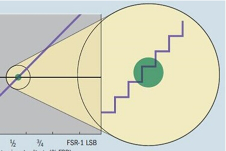
The resolution of the A/D converter is defined as the minimum change in the value of the input signal, which can be changed by one count. In the case of an ideal A/D converter, the transfer function is stepped and each step width is equal to the resolution. However, when using a higher resolution (16-bit or more) system, there will be a large deviation between the response of the transfer function and the ideal response. This is because the noise generated by the A/D converter and the driver circuit can reduce the resolution of the converter.
In addition, if a direct current (DC) voltage is applied to the input of an ideal A/D converter and multiple conversions are performed, the digital output should always be the same code. But in reality, the output code becomes multiple codes and is distributed in multiple locations (see the red dot cluster in the figure below), depending on the total noise of the system. Other factors include the voltage reference and the driver circuit. The more noise in the system, the larger the clustering of data points, and vice versa. Figure 1 shows an example of a half-scale DC input. In the product specification of the A/D converter, such an output point cluster on the A/D converter transfer function diagram is typically represented as a DC histogram.
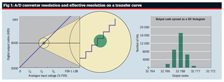
The illustration in Figure 1 brings an interesting question. If the same analog input can produce multiple digital outputs, does the definition of the A/D converter resolution still apply? The answer is yes - but the premise is that we have to consider the quantization noise of the A/D converter. However, when we explored all the noise and distortion in the signal chain, we found that the noise-free effective resolution of the A/D converter is determined by the output code spread (Npp) condition.
Noise-free resolution = log2 (2n/Npp)
Where n is the ideal resolution
In a typical A/D converter product specification, the effective number of bits (ENOB) is determined indirectly by the alternating current (AC) parameter and the signal-to-noise ratio (SINAD). The ENOB can be calculated using the equation below:
ENOB = (SINAD-1.76) / 6.02
Next, please take a closer look: Is the output code cluster (green cluster in Figure 1) not only centered on the ideal output code, but instead located elsewhere on the A/D converter transfer curve, away from the red dot? This distance is an indicator of the accuracy of the data acquisition system. The A/D converter, as well as the front-end driver circuit, reference and reference buffers, are all factors that affect the overall system accuracy.
It should be noted here that the accuracy and resolution of the A/D converter are two different parameters, which may not be equal to each other. From a system design perspective, accuracy can determine the overall error budget of the system, while system software algorithm integrity, control, and monitoring capabilities depend on resolution.
The difference between A/D converter resolution and accuracy has been determined, and we can now delve into the factors that can affect the overall accuracy of the converter, often referred to as unadjusted total error (TUE).
Have you ever thought about what does “total†mean in the unadjusted total error (TUE) specification of the A/D converter? Is it just simple to add all the DC error specifications from the product specification, such as offset voltage, gain error and integral nonlinearity (INL) error, or have a deeper meaning? In fact, TUE is the ratio of the total system error to the input range of the converter's operation.
More specifically, TUE is a DC error specification expressed in units of least significant bits (LSBs) representing the maximum deviation between the actual transfer function of the A/D converter and the ideal transfer function. This specification assumes no system level calibration.
Conceptually, TUE reflects the combined effects of the following types of non-ideal factors in the operation of the A/D converter:
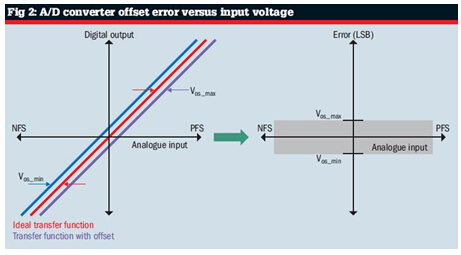
· Offset error (VOS). This error is a constant difference between the actual transfer curve of the A/D converter and the ideal transfer curve (see Figure 2). It is the measured digital output obtained by shorting the A/D converter input to ground (GND).
· Gain error. The difference between the actual slope and the ideal slope of the A/D converter output. It is usually expressed as the ratio of the A/D converter range or maximum error at the full-scale code. As shown in Figure 2, as the analog input approaches the full-scale value, the absolute value of the gain error increases.
· Integral nonlinearity (INL) error. The maximum nonlinear deviation between the actual transfer curve of the A/D converter and the ideal linear mode of operation. The INL response diagram of the A/D converter has no fixed shape, depending on the internal circuit architecture and the distortion caused by the front-end signal conditioning circuitry.
Most A/D converter product specifications specify typical values ​​and maximum values ​​for all of the above DC errors, but TUE is not assigned this value. Calculating the maximum value of TUE may not be as simple as summing the maximum of all individual DC errors. The reason is that all of these errors are irrelevant, and the worst case is that offset, gain, and linearity errors may not all occur at the same input voltage on the transfer function of the A/D converter. Therefore, simply adding the errors may make the system look too bad. This is especially the case if the dynamic range of the application is limited to a position near the middle of the transfer function.
In a typical data acquisition system, there is an input driver associated with the A/D converter and a voltage reference, both of which increase the total offset and gain error. Therefore, when calculating the TUE maximum in most systems without calibration, the offset and gain errors will be larger than the INL error. To calculate the maximum TUE for a particular analog input voltage, the recommended method is to take the sum square root of all individual error maxima at that point. It is important to convert all these errors into the same unit (usually the LSB).
TUE = v[|VOS|2 + gain2 + INL2]
With this equation, an error map of the shape of a "bow" is usually generated. For systems with higher offset errors, the "bow" knot is thicker. But for systems with higher gain errors, the "bow" knot becomes thinner and the bow becomes thicker.
In summary, there is no formula for calculating the TUE maximum for the A/D converter, since this error depends on the input range when the A/D converter is operating. If the system does not require the entire input range of the A/D converter, the engineer can minimize TUE by moving the device away from the endpoint of its transfer function.
Microstepping is a method of controlling stepper motors, typically used to achieve higher resolution or smoother motion at low speeds.
Micro Stepper Motor divides each full step into smaller steps to help smooth out the motor`s rotation, especially at slow speeds.
Microstepping is achieved by using pulse-width modulated (PWM) voltage to control current to the motor windings. The driver sends two voltage sine waves, 90 degrees out of phase, to the motor windings. While current increases in one winding, it decreases in the other winding. This gradual transfer of current results in smoother motion and more consistent torque production than full- or half-step control.
Micro stepper motor,Micro linear stepper motor,Micro stepping stepper motor
Shenzhen Maintex Intelligent Control Co., Ltd. , https://www.maintexmotor.com