
Due to its high illumination efficiency, long-term efficiency and small size, LED has become an inevitable choice for portable devices such as mobile phones and PDAs. A low-power white LED of about 0.1W is currently widely used in the backlight and keyboard of LCD display panels. Lighting, of course, can also be connected to multiple LEDs to bring higher brightness for temporary lighting or flash applications, while high-power LEDs up to 1W are used in camera phones with 2 megapixels or even higher resolution. Medium to support camera functions in dark environments. In addition to white LEDs, RGB (red, green, blue) LEDs are often used to enhance the texture of mobile phones. RGB LEDs create a rich variety of colors by precisely mixing them in three colors.
This article refers to the address: http://
In the indicator application, when there is an incoming call or message, the color LED can be flashed, or the color can be used to display the identity of the caller, such as a self-defined group, such as a friend, family member or a business call, this function is not only for mobile Personalization of the phone is also very useful in very noisy environments. In order to further enhance the user's audio and video experience, RGB LEDs are also used to generate a lot of attractive lighting effects. One example is to synchronize the RGB lighting action with the ringing melody or MP3 music, and another interesting application of RGB lighting. It is the "Feel Talk" function of Panasonic Corporation of Japan. Since the RGB LEDs are arranged under the casing of the mobile phone, different colors can be displayed according to the user's mood.
Major white LED suppliers
Currently used in the portable device LCD and keyboard backlight white LED, was introduced by Nichia Chemical Company in 1996, through the coating of gallium nitride (GaN) with pale yellow fluorescent material. A blue LED of indium gallium nitride (InGaN) is used to achieve a white light effect. In addition, the development of blue and green LEDs has expanded the richness of LED color output.
However, in the late 1990s, multiple patent infringement issues between major LED manufacturers in Japan, the United States, and Europe prevented new manufacturers from entering the market. Fortunately, these legal proceedings were gradually resolved through mutual authorization negotiations, and some manufacturers such as Nichia, ToyodaGosei, Cree, Philips Lumileds and OSRAM established their leading position at that time. In addition, newcomers in Taiwan and South Korea began to rise a few years ago, and in the past two years they have gradually tasted the fruits of high turnover.
LED performance has increased dramatically
After the development of a large number of funds betting LEDs, the lighting efficiency of white LEDs has been greatly improved compared to the original invention. The best white LED lighting efficiency on the market can reach 100lm/W, which is quite close to fluorescent tubes, and some leading companies. Attempts have also been made to use different coating materials on blue LEDs and to introduce a design with better luminous efficiency, so the number of LEDs required to provide panel backlighting will continue to decline. Currently, the backlight LED required for standard LCD panels on mobile phones is approximately 2~4, and the backlight of the LCD panel on PDA or smart phone needs 6~10. Before discussing the drive circuit structure and new functions of LED backlights and flash lamps, let's review the electrical characteristics of LEDs and batteries widely used in mobile phones and PDAs.
Depending on the technology used by different manufacturers, the forward voltage (Vf) of the LED is between 2.7 and 4V. Usually high-power LEDs have a high forward voltage of up to 4.9V, so the LED driver circuit must provide enough A positive voltage is used to cause the LED to illuminate in a forward biased manner. When multiple LEDs are used to provide backlighting, the difference in forward voltage should be considered in the design of the driver circuit. In order to achieve the same illumination intensity, that is, different LEDs emit the same color, the design engineer must ensure that each pixel flows through each The forward current of the LED can be the same. The low-power LED usually uses a forward current of 20mA, and the maximum is about 25mA. The high-power LED on the market can be driven with a pulse current of up to 1.5A.
At present, the most common battery type in mobile phones and PDAs is lithium ion or lithium polymer rechargeable batteries. The rechargeable battery with lithium material has a standard voltage of 3.6V to 3.7V and an operating voltage of 4.2V to 3.2V. Safe operation, this type of lithium material battery can only be charged or discharged within 1C range, where C is the specification capacity of the battery, for example, the maximum discharge current of the battery is 1,000A for mAh, and the battery capacity is usually used by the mobile phone. Between 650mAh and 1000mAh. Newer state-of-the-art lithium-ion batteries with different cathode materials have been developed to improve battery performance. When using such battery packs, design engineers should follow electrical specifications and adjust the drive circuit accordingly.
Let us now further study the application of LEDs in LCD backlights, decorative light sources and camera flashes.
LCD backlight
When using LEDs with a maximum forward voltage of 3.4V to 4V, the input voltage supplied by the battery must be equal to or higher than the required drive voltage, so a boost converter with a stable current function is required to push in series or LEDs connected in parallel.
Charge Pump / Switched Capacitor Converter Charge Pump Converter is widely used in backlighting of LCDs. Compared with inductive boost converter solutions, charge pump drive circuits have lower cost and thinner thickness. As well as lower noise characteristics, it is a better choice. The new integrated circuit design has gradually improved the efficiency of the charge pump drive circuit. The current maximum efficiency can exceed 93%, and the average is about 80%.
Progressive brightness changes and progressive lighting changes in contextual lighting are mainly used to create a theater-like lighting effect when the portable device is turned on or off. At startup, the backlight current is stepped in a step-by-step manner according to a preset time interval. Zooming in to 20mA, similarly, when the power is turned off, the opposite action is gradually reduced. With the help of the microprocessor, the PWM signal with different frequencies can be sent to the start pin of the LED driving circuit to achieve this effect. The LED current is increased or decreased in multiple steps at specific time intervals, but this method has the disadvantage of consuming instant processor resources, so this function is built into the LED driver chip products such as the NCP5602 and NCP5612. In the wafer (Figure 1).
Â
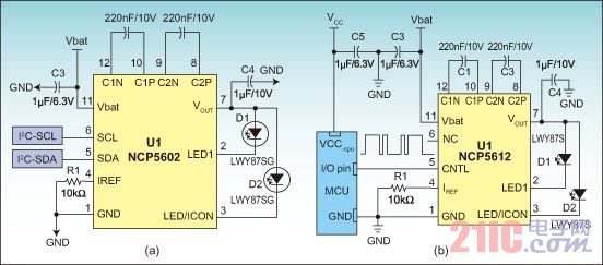
Figure 1: Typical 2 LED Charge Pump Driver Application
Â
These driver chips require two flying capacitors, output and input capacitors, and a resistor (R1) to control the highest output current. The progressive brightness change control command is sent by the processor through the I2C port or the output pin. For the wafer, the instruction itself should contain the time interval between the initial and final current levels and the change in brightness.
When applied to RGB LEDs, such a function can be used to create contextual lighting effects. With 32 bright and dark steps for each RGB LED, 32,768 LED driver chips like the NCP5623 can be used. Color changes, through this light and dark step and built-in logarithmic algorithm, can create a fairly smooth and linear color change for the eyes, RGBLED driver circuit contains independent control to adjust the output current of 3 LEDs The PWM current source is used to produce the desired color output (see Figure 2).
Â
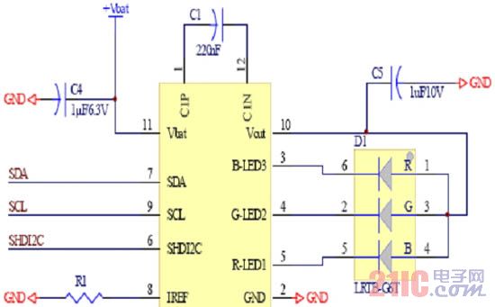
Figure 2: Typical RGB LED driver chip application with I2C control interface
Â
Since the timing and current of each current output can be independently controlled and adjusted, white light or colored LEDs can be used to express the output of different illumination modes for decoration or indication purposes. Some circuits with audio input can also make color LEDs. Synchronize with different frequency bands of internal MP3 or polyphonic ringtones.
ICON mode Have you ever tried to watch your phone in a dark environment, when the strong contrast between the bright backlight and the dark environment is quite uncomfortable for the eyes, which is why there is a ''ICON mode'' design. In standby mode, the external LCD panel is illuminated with a small current to display time or a specially defined image, but if this must be achieved by PWM shading control, then the processor must generate a continuous low frequency PWM in the entire standby mode. Signal, in the NCP5602, this function is implemented in hardware and can be started by a digital command as shown in Table 1.
Â
![]()
Table 1: I2C internal scratchpad location arrangement for NCP5602
The B5 sent from the processor to the driver chip data byte represents the state of the ICON mode. When B5 is LOW, it indicates that the normal backlight mode is used, and the current of each LED can be adjusted from 0 mA to a maximum of 30 mA. When B5 is HIGH, ICON mode is started, and only 450μA current is sent to one of the two connected LEDs. In this component, the current value of ICON mode is fixed, but on similar component NCP5612, this current It can be controlled by a single-wire communication protocol. Figure 3 shows the ICON control program for the SCL and SDA lines in the I2C communication protocol.
Â
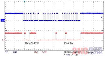
Figure 3: Sequence of data on a simple SCL and SDA connection line for ICON mode control
Â
Linear Regulator/Current Source Solutions When using a clustered LED with a low forward voltage of approximately 3.3V, a linear regulator can be selected to provide the drive current. Compared with switched converters, linear regulators have lower cost and lower electromagnetic interference because linear regulators only need to add several resistors around the periphery of the driver chip, without the need for switching components, but this type of solution The shortcoming of the solution is the narrow effective battery voltage operating range. Figure 4 shows the use of the NUD4301 low-dropout linear regulator as the two LED driver circuits. The standard 0.2V voltage drop and 3.3V LED forward voltage are considered. The regulator will leave regulation mode and enter saturation mode when the battery voltage is below 3.5V, which will cause the regulator output current to drop sharply while the LED brightness begins to dim, but if the minimum battery voltage is within acceptable limits , then linear regulators are also the most cost-effective backlight solution for small LCD panels.
Â
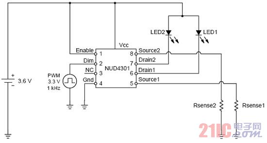
Figure 4: Using the linear regulator NUD4301 as the two LED driver circuits to drive the backlight of a small LCD panel
Â
Mobile lighting application
The LED lighting function provided by the Temporary Lighting Phone is generally considered to be a very sophisticated design, which can be seen by many flashlights now consisting of several low-power LEDs and driven by the lower current drive from 20mA to 60mA. Lighting can be used as a portable flashlight, but its faint illumination intensity is not enough to support photography in dark environments. In fact, one or more high-power LEDs must be supported to support 1 meter or more of shooting illumination. The main reason that hinders engineers from joining high-power LEDs is cost. Currently, high-power LEDs produced in mass production rely mainly on the supply of the top five manufacturers in the world. However, after the power LED capacity of Taiwanese and Korean manufacturers is gradually opened, the unit price is expected to start to decline. At the same time, the cost of the drive circuit will also decrease with mass production.
A single high-power flash drive circuit boost converter is required to support up to 4.9V forward voltage in high-power LEDs, but even with the same LED chip, the forward voltage will vary under different conditions. When the LED temperature rises, the forward voltage may slip below the input battery voltage, so a buck converter is required. Technically, the buck-boost converter is the best solution for driving a single high-power LED. However, such driver chips are generally costly, and they also need to be matched with external inductors that increase cost and size. The advantage of the buck-boost converter is the higher overall efficiency. The main reason is the full use of the battery energy, while providing ultra-high output current of more than 1A or higher. The new high-current charge pump drive circuit is liter. A low-cost alternative to buck converters, however, the charge pump converter's output current is up to approximately 700 mA, which is primarily limited by the lower efficiency and the maximum current that can be drawn by the battery.
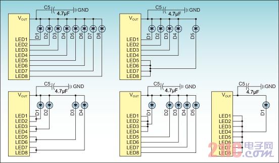
The integrated lighting management chip has backlighting and flashing capabilities, and some integrated lighting management chips (LMICs) with RGB and other audio and video functions are now on the market, including boosts that may use a charge pump or inductive design. The converter, each output is provided by an adjustable current source, which is especially useful in a flip-top or slide-type phone because it eliminates the long path required to pull the power management unit to the other side of the phone. The NCP5608 is an integrated charge pump driver chip that can deliver up to 500mA total current with 8 outputs. The output current can be adjusted by the processor through the I2C port, and can also be configured to meet different LED configurations. Please refer to Figure 5 for the requirements of various platforms.
Â
Â
At present, the most common battery in mobile phones and PDAs is lithium ion or lithium polymer rechargeable batteries. The rechargeable battery with lithium material has a rated voltage range of 3.6V~3.7V and the working voltage is 4.2V~3.2V. It can work safely. This type of lithium battery can only be charged or discharged in the range of 1C, where C is determined by the rated capacity of the battery. For example, the maximum discharge current of a battery of 1,000mAh is 1A, and the battery capacity normally used by mobile phones is about Between 650 and 1,000 mAh. In order to improve the performance of the battery, a new lithium ion battery using different cathode materials has been developed. When using this type of battery pack, the design engineer should follow the electrical specification limits and adjust the drive circuit accordingly.
When using an LED with a maximum forward voltage of 3.4V~4V, the input voltage supplied by the battery must be equal to or higher than the required driving voltage, so a boost converter with a stable current function is required to push in series or LEDs connected in parallel.
Charge pump converters are now widely used in backlighting of LCDs. Compared to inductive boost converter solutions, charge pump driver circuits are characterized by lower cost, thinner thickness, and lower noise characteristics. A better choice, the new integrated circuit design has gradually improved the efficiency of the charge pump drive circuit, the current maximum efficiency can exceed 93%, and the average efficiency is about 80%. The charge pump drive circuit usually operates in 1x and 2x modes. Some devices have added 1.33x and 1.5x modes to improve efficiency. In this type of solution, the LEDs are connected in parallel, and the current of each LED is provided by separate matching current sources. The best driver chip is The matching error between any two LED currents in the same circuit is about 0.2%.
Â
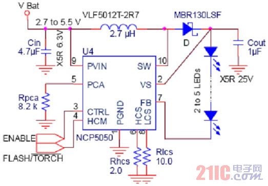
Figure 6: 4.5W Power Flash Drive Circuit with Internal Switch and Time Limit Protection
Summary of this article
The mass supply of LEDs has made the price of low-power LEDs for LCD panel backlights on mobile phones and PDAs lower and lower. The newly-launched backlight driver chip also incorporates step-by-step brightness control and does not require any software design. Situational lighting control that consumes any microprocessor resources, and these LED driver circuits can help portable product manufacturers reduce development time. On lower cost solutions, linear regulators can be used to drive LEDs with lower forward voltages. On the other hand, several flash drive solutions are also available on the market. They are independent buck-boost converters, high-current charge pump drive circuits, and lighting management chips. Most power flashes may contain several standard LEDs or one high-power LED. The main reason why high-power LEDs are not popular in camera phones today is the higher unit price. Two LEDs are used in some high-end mobile phones to provide a higher-brightness flash to enhance the camera's camera. With the trend of camera phones gradually replacing digital cameras, higher power flash solutions will become more popular, providing users with a true camera experience.
Cement resistance: is the resistance wire wound on the alkali heat-resistant porcelain, coupled with heat resistant, resistant to wet outside fixed protection and corrosion resistance of the materials and the winding resistance into the square porcelain box body, using special incombustible cement packing seal.The outside of cement resistance is mainly made of ceramic materials (generally divided into high alumina porcelain and feldspar porcelain).
Cement Resistor,Thermal Cement Resistor,Thin Film Cement Resistor,Winding Cement Resistor,Fusing Cement Resistor
YANGZHOU POSITIONING TECH CO., LTD , https://www.yzpstcc.com