
Abstract: For the collision avoidance warning of trains on the same track, GPS satellite positioning and track estimation are used to achieve combined positioning. Through wireless data transmission technology, it can be used for local railway network traffic under complex orbital geographical environment (tunnel, forest, hill, etc.). Security management. Experimental tests have shown that the system can meet the application requirements.
This article refers to the address: http://
0 Preface
Collision avoidance is an important research issue in the field of modern transportation. It is closely related to people's lives. There are many studies in the fields of aviation, navigation, roads and rail transit. For example, the traffic warning and collision avoidance system/self-decision supervision broadcast system TCAS/ADS-B in the aviation field; the ship automatic identification system AIS in the maritime field; the car-vehicle collision avoidance system C2C ​​in the road traffic field.
In the fields of road traffic, aviation and navigation, there are already mature anti-collision warning systems. In contrast, the research on anti-collision early warning systems in the field of rail transit started late and the development is actually more difficult. This paper mainly deals with the operation of low-speed freight trains under complicated orbital geographical conditions (tunnels, forests, hills, etc.), rational use of single-chip technology, GPS satellite positioning technology and track estimation navigation algorithm to design low-cost railway train collision avoidance. system.
1 System overview
The train anti-collision warning system consists of a positioning system, a wireless communication mechanism, a decision system, and an alarm device. Its system structure is shown in Figure 1.
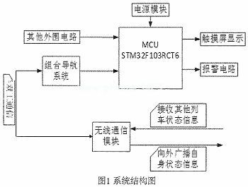
After the system is started, its own information (real-time location, real-time speed, etc.) is first broadcast to the nearby area, and other broadcast information of the system in the area is received. Through these information received from other trains, the train can fully understand the traffic conditions in the vicinity, and if there is a possibility of danger, immediately provide warnings and suggestions to the train crew to avoid collision accidents. Therefore, the anti-collision warning system mainly has three functions: 1 position, speed and other related information acquisition; 2 broadcasting and receiving the related information; 3 processing the information and detecting whether there is a collision risk, and if present, issuing an alarm signal.
2 integrated navigation system
The integrated navigation system is mainly to provide reliable position information for the train anti-collision warning system, and the real-time positioning information of the train is crucial for the collision detection of the train control and the system.
2. 1 GPS Global Positioning System
The basic principle of GPS (Global Positioning System) positioning is based on the instantaneous position of the satellite moving at high speed as the known starting data, and the spatial distance intersection principle is used to determine the position of the point to be measured. The developed automatic occlusion system on the railway has confirmed that GPS is suitable for train positioning. GPS positioning does not depend on other trackside equipment. Only a high-precision GPS terminal receiver can achieve conventional positioning. However, GPS has the disadvantages of poor dynamic response capability, vulnerability to electronic interference, and easy occlusion of signals. If the GPS signal cannot be recovered in time for a long time, the system error will inevitably accumulate at any time. When the train is driving in a tunnel or forest with poor GPS signals, pure satellite positioning will not meet the system requirements.
2.2 DR track estimation positioning system
DR (Dead Reckoning) is a navigation and positioning method that uses the known initial position of the carrier to calculate the coordinate position of the next moment in real time according to the heading, speed and navigation time of the moving carrier at that point. It is an autonomous positioning, and its positioning accuracy is not affected by external factors such as electromagnetic interference and occlusion. However, the track estimation system does not have long-term stability and must be corrected at intervals. The trajectory estimation system used in this system is similar to the vehicle odometer. Its structure and principle are also the same. It consists of a magnetic sensor and a set of magnetic sheets attached to the wheels. Each rotation of the wheel, magnetoelectric The sensor generates a certain number of pulses. By counting these pulses, the train travels during this time, and the train travel time at the time is
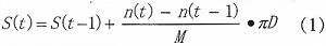
Where n(t) is the number of pulses output at time t: n(t)-n(t-1) is the number of output pulses in this cycle; M is the number of pulses that should be output per revolution of the wheel; For the wheel diameter.
According to the train running time at time t, the running speed of the train is
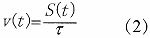
Where Ï„ is the counting period, and when the counting period is small, the speed can approximate the instantaneous speed of the train.
2. 3 integrated navigation algorithm
When the train is running in a satellite signal such as a tunnel, the system will automatically record the effective coordinates of the last GPS output. At the same time, the DR system uses the point as the coordinate coordinate origin of the geographic coordinate system (usually take the east, north, and day). The coordinate system, which satisfies the right-hand rule) is used as the reference coordinate system for the estimation of the track, and takes the point as the starting point of the estimated position. The heading sensor and the DR system can be used to determine the position of the vehicle at each moment:
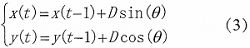
Where x(t), y(t) is the position of the train in the reference coordinate system at time t; x(t-1), y(t-1) is the position of the train in the reference coordinate system at time t-1 ; θ is the angle between the direction-finding speed and the north direction of the reference coordinate system. Here, we make a reasonable simplification of the tunnel. In general, we think that the tunnel is a straight tunnel. Therefore, the track estimation can be performed according to the effective coordinates of the last GPS output recorded by the system in combination with the real-time position of the train:
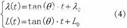
In the formula, λ(t) and L(t) are the real-time longitude and latitude of the train during the track estimation process; λ0 and L0 are the starting point latitude and longitude, respectively.
3 hardware design
3.1 Integrated Navigation Module
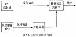
GPS positioning has long-term stability, but the positioning is not continuous. The track estimation system has good short-term stability, but the positioning error correction must be performed at regular intervals. It can be seen that GPS positioning and DR have strong complementarity. The system adopts GPS/DR combined positioning system. Through DR positioning error compensation, it ensures that the train can effectively determine the real-time position of the train when the GPS signal is lost. The structure of the combined positioning system is shown in Figure 2.
Often used for both interior and exterior Illuminated Acrylic Signs, these illuminated Neon Signage include everything your business might need from logo, products, open time, home & festival decoration, lighting and advertisement.
Safe & low voltage, low power consumption, because the light source is LED, so even in the case of 12V, it can work normally.
Illuminated Signage,Illuminated Acrylic Signs,Outdoor Led Illuminated Signs,Illuminated Signage Letters
Shenzhen Oleda Technology Co.,Ltd , https://www.baiyangsign.com