
1 Introduction
This article refers to the address: http://
At present, although the engines of medium and high-end cars produced in China have basically adopted the fuel-electric fuel injection technology, and the components of the EFI system have basically possessed the supporting research and development capabilities and production capacity, but there is no independent intellectual property rights of the EFI engine. All belong to the introduction of foreign EFI engine production lines or EFI systems. In particular, the ECU (Electronic Control Unit) as the core component is mastered by foreign companies, and the fuel injection and ignition MAP, control algorithms and programs in the ECU are completely confidential. At the same time, there are many importing countries and various types of specifications. Some enterprises lack the choice of argumentation. The introduced technical level and product quality are uneven, and many lack sufficient matching experiments.
This research project is an ECU that uses people, vehicles and the environment as an integrated system to comprehensively coordinate various factors to make the control performance of the vehicle tend to be optimal. Therefore, with high economic and social benefits, it will promote the application of industrial control networks and embedded control systems in the automotive industry, making cars more intelligent and user-friendly.
2 Research content
The main control objects of this project are fuel injection and ignition devices. There are also some related auxiliary control functions. mainly include:
(1) Intelligent Fuel Injection Control IIC (Intelligent Injection Control), mainly including fuel injection quantity, injection timing, fuel stop supply and oil pump control. Due to the intelligent design, the solution to the problem of the fixed control algorithm can effectively save fuel and contribute to the overall performance improvement.
(2) Intake control, mainly including power valve and vortex valve control, can effectively improve and improve the output torque and power of the engine.
(3) Pressure control, the ECU controls the pressure release solenoid valve according to the intake pressure signal detected by the intake pressure sensor to control the exhaust passage switching valve, change the direction of the exhaust passage, thereby controlling the exhaust turbocharger to enter the work Or stop state.
(4) Electronic ignition control ESI (Electrical Spark Ignite), the ignition device control mainly includes ignition advance angle control, energization time (closed angle) and constant current control, knock control and so on.
(5) Idle (Idle Speed ​​Control), the engine is controlled by the ECU under different idle operation conditions, such as car operation, air conditioner compressor operation, transmission-in gear position, and generator load increase, so that the engine is controlled by the ECU. Can operate at the optimal idle speed.
(6) Emission control, control items mainly include: Exhaust Gas Recirculation Control, oxygen sensor and three-way catalytic open loop and closed loop control, secondary air injection control, activated carbon tank solenoid valve control, etc.
(7) Warnings and prompts, the ECU controls various prompting and warning devices to display the working status of the control system and issue a warning signal if the control system fails.
(8) Sensor fault pre-diagnosis reference system (failure protection), when the main ECU detects a sensor or line fault, it will follow the set value provided by the main ECU pre-program, so that the engine can still keep running, but the performance will be reduced. .
(9) The main ECU fault backup redundant system, when the main ECU fails, the standby redundant system is automatically activated to make the engine into a forced running state, so that the driver can drive it to repair.
3 The composition of the EFI system
In addition to the power supply, power-off device, ignition device and starting device of the general carburetor engine, the electronic fuel injection system also has an electronic fuel injection control device, an idle speed control device, an electronic control unit ECU and various signal acquisition devices (sensors). . Figure 3-1 shows the composition of an electrospray system.
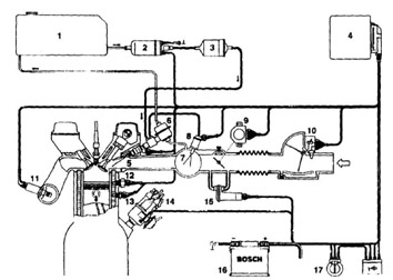
Figure 3-1 Basic composition of the EFI system
Fig.3-1 the basic composition of electronic injection system
1. Fuel tank; 2. Electronically controlled oil pump; 3. Fuel filter; 4. ECU; 5. Fuel injection valve; 6. Fuel control valve and oil pressure regulator; 7. Intake manifold; 8. Cold start valve ; 9. throttle position sensor; 10. air sensor; 11. oxygen concentration sensor; 12. hot time switch; 13. water temperature sensor; 14. ignition distributor; 15. idle actuator; 16. battery; Start switch
The EFI system shown in Figure 3-1 can be divided into three parts: the actuator, the signal acquisition device, and the signal processing control device. The relationship between them is shown in Figure 3-2.
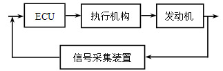
Figure 3-2 Relationship between various parts of the EFI system
Fig.3-2 the relation for parts of electronic injection system
Actuators include injectors, ignition coils and spark plugs, and idlers. The collected signals are: throttle opening, intake manifold pressure, speed, knock signal, body cooling water temperature, exhaust gas oxygen concentration, intake air temperature. As a signal processing control device, the ECU converts the signal into a recognizable value through a series of processing, and then obtains a control signal of the output actuator through calculation.
The control accuracy of the ECU must be accurate in addition to the required real-time and accurate signal acquisition. The use of some algorithms in the ECU control program can not only achieve higher control accuracy, but also compensate for some errors caused by non-real-time signal acquisition and low motion accuracy of the actuator.
4 ECU
Through the analysis of the composition of the EFI system, we can clearly see the important position of the ECU as the control core. Due to the time-varying and non-linearity of the control object, the engine control system using ECU has been developed to the centralized control system: in the control structure, the ECU is the core, and the communication is established with the I/O device through the CAN bus; in the control algorithm, The model of steady state controlled MAP and idle speed control is constructed by the combination of fuzzy control theory, PID regulation and BP neural network. Figure 4-1 shows the control structure of the EFI system.
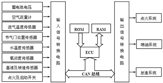
Figure 4-1 EFI system control structure
Fig.4-1 the control structure of electronic injection system
The CPU of the ECU adopts a DSP chip with floating-point operation capability, and each detection signal and drive control circuit can adopt an independent single-chip microcomputer or a CAN bus interface with A/D and switching amount conversion. After the structure is determined, the control ability of the ECU lies in the development of the control program. Since the control state and strategy are complicated, the following takes ESI as an example.
The core issue of ESI control is the control of the ignition advance angle. The control strategy is completely different under different working conditions: when the engine is in the starting condition, because the starting speed fluctuates greatly and fast, it is impossible to determine the ignition advance angle according to the MAP map; when the engine is in the transient working condition, Because it is open-loop control, the ignition advance angle can be directly calculated by interpolation method; when the engine is in steady state condition, it is necessary to judge whether or not to detonate, and accordingly, closed-loop control is adopted, that is, the previous MAP map value is stepwise adjusted. To obtain the optimal ignition advance angle. Figure 4-2 is a flow chart of the control routine for the ignition advance angle.
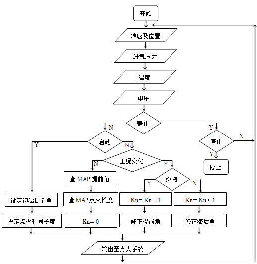
Figure 4-2 Flow chart of the ignition advance angle control program
Fig.4-2 the control procedure flow chart of ignition angle
5 Conclusion
Based on the analysis and summary of the existing research results of the existing systems and related researches at home and abroad, this paper proposes the design scheme of the intelligent electronic controller of the automobile engine based on CAN bus, and further simulates the various parameters. The experiment will finally give the intelligent MAP and control program for various working conditions.
Robot Cleaner,Wet Dry Vacuum Cleaner,Wifi Robot Cleaner,Vacuum Cleaner Robot
Robot Lawn Mower,Robot Humidifier Co., Ltd. , http://www.zd-machinery.com