
1. PLC Communication Port Damage Case
We encountered a situation in a project where the PLC communication port was damaged. The communication lines from the PLC were routed through a slip ring. Considering that it had rained a few days prior, we suspected that water had entered the slip ring and caused a short circuit in the communication line, ultimately leading to the damage of the PLC port.
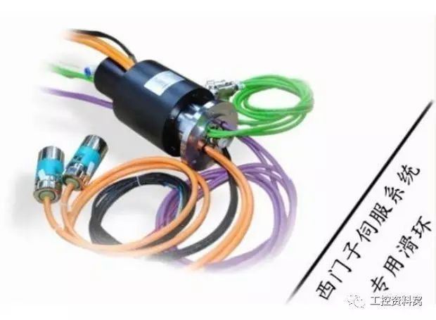
To investigate, we used a megohmmeter to test the communication lines, with both ends disconnected. Normally, the resistance should be infinite, but we found a resistance between 5MΩ and 10MΩ. This indicated a partial short circuit due to moisture. After replacing the slip ring, the system returned to normal operation.
2. Avoid Repeated Subroutine Calls
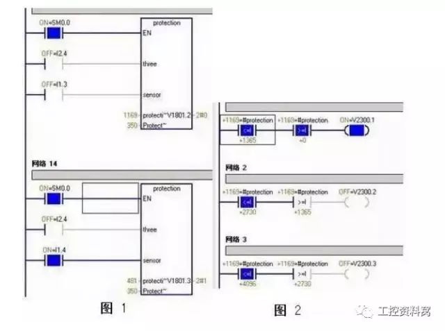
In our program, the same subroutine was called multiple times. While there were no syntax errors, repeated calls—especially when involving parameters—can lead to unexpected behavior. For example, if two different network sections call the same subroutine with different parameter values, the last call might overwrite previous settings, causing inconsistencies.
As shown in Figure 1, both Network 13 and 14 call the protection subroutine. When Network 14 is executed, the value of the parameter #protection (which should be 481) is not correctly set, as it retains the value from Network 13 (1169). This can lead to incorrect logic execution, which is hard to debug.
3. PLC Input Line Capacitance Causes Malfunction
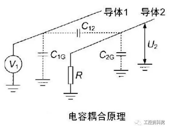
Cable capacitance is a common issue in PLC systems. Even qualified cables have some capacitance between their conductors. However, when the cable length exceeds a certain limit, this capacitance may exceed acceptable levels, leading to interference between input signals.
Recently, during system debugging, we noticed an unusual phenomenon: when the MIC sensor was inactive or after it operated, the FLY sensor's action would interfere with the MIC sensor, causing it to become unresponsive. This suggested that the cable’s capacitance was too high, creating cross-talk between the sensors.
After bypassing the cable and directly connecting the MIC sensor to the PLC, everything worked as expected. To mitigate such issues, consider the following:
(1) Use twisted pair cables;
(2) Keep cable lengths as short as possible;
(3) Separate signal cables from power lines;
(4) Use shielded cables for sensitive inputs.
4. PLC Programming to Prevent Misoperations
(1) Eliminate Bounce Effects
Use the DIFU instruction (13) to detect the rising edge of a button press signal. This ensures that the PLC only triggers once per cycle, preventing misoperations caused by mechanical bounce.

(2) Prevent Unintended Operations
Optimize the display function by using different indicator lights to show various working states. For instance:
- Steady light: Running state;
- High-frequency flash (1 second): Test mode;
- Low-frequency flash (3 seconds): Step-by-step mode.
Additionally, implement input signal interlocks to prevent conflicting operations.
5. Inverter Overvoltage Example
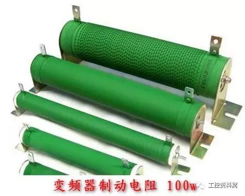
When a motor decelerates via the speed setting, it enters regenerative braking mode, feeding energy back into the inverter. This energy accumulates in the DC bus capacitor, increasing its voltage rapidly. If the overvoltage threshold is exceeded, the inverter will trip.
Solution: Install a braking resistor externally. This resistor dissipates the excess energy, preventing the inverter from tripping due to overvoltage.
6. Inverter Overcurrent Example
We experienced an overcurrent fault on a Yaskawa inverter connected to 120 small motors. When one motor had an overcurrent condition, the inverter tripped, causing all other motors to stop unexpectedly. This was an undesired outcome.
Solution: Install a 1:1 isolation transformer on the inverter’s output. This prevents fault current from directly reaching the inverter, allowing it to remain operational even when one or more motors experience overcurrent. After testing, the system performed well, and no further trips occurred.
Empowering Natural Expression:Active Stylus Pens are not just about tapping and swiping; they're designed for those who demand the finesse of a pressure-sensitive tip for detail-oriented work. Artists, note-takers, and design experts will find these pens transform their touchscreen into a canvas or notepad with responsiveness akin to classic penmanship.
Enhanced Functionality for Modern Needs:These pens are loaded with features like palm rejection and adjustable pressure sensitivity, perfect for professionals who need their digital strokes to keep pace with their imagination. Added shortcuts and customizable buttons further refine the user's workflow.
Compatibility and Sleek Design:Most Active Stylus Pens are now universally compatible, making them versatile tools across various devices. Their design is sleek, marrying form with function to offer a comfortable tool for all your digital sessions.
Exploring the Stylus Pen Landscape:Our assortment includes:
Capacitive Stylus Pens: Enjoy seamless interaction on your device screens with these responsive pens.
Stylus Pencils: These mimic traditional pencils but are engineered for modern touchscreens.
Tablet Pencils: Created for tablet users, these feature advanced functionalities to cater to creative professionals.
In the world of Active Stylus Pens, we provide a diverse range of products to suit different roles and functions. These tools are created to unleash your creativity and efficiency, enhancing your digital life. Dive into our selection and find your perfect Active Stylus Pen partner for your touchscreen adventures.
Active Stylus Pen,Stylus Pencil,Capacitive Stylus Pen,Tablet Pencil
Shenzhen Ruidian Technology CO., Ltd , https://www.wisonen.com