
In the security monitoring system, video signal transmission is a crucial link in the entire system. The choice of media and equipment to transmit video signals will directly affect the quality and reliability of the monitoring system. At present, the media used to transmit video signals in the monitoring system mainly include coaxial cables, twisted pairs and optical fibers, and the corresponding transmission devices are coaxial video amplifiers, twisted pair video transmission equipment and optical transceivers.
Coaxial cable was used earlier and is also the longest used transmission method. Later, due to the need for long-distance and large-scale image surveillance and the improvement of people's requirements for surveillance image quality, a large number of optical fibers were used in surveillance networks to transmit video signals. As for the use of twisted-pair cable in video surveillance networks, it is a recent matter. Its emergence mainly solves two problems: on the one hand, it solves the transmission of high-quality video signals within a distance of 200 meters to 2000 meters. Problem, because it is difficult to meet the requirements of coaxial cable transmission and optical fiber transmission is uneconomical within this distance; on the other hand, it solves the wiring problem of large-scale intensive monitoring networks, the size and flexibility of the twisted pair itself Overcome a lot of wiring problems when using coaxial cables. Of course, twisted pair also has the advantages of strong anti-interference ability and low price. It is precisely because the twisted pair has solved these problems that have troubled people for a long time, so its application in the monitoring network has immediately attracted widespread attention in the industry, and has been widely used in engineering practice in a short period of time, and Good application results have been achieved.
Typical application of video signal twisted pair transmission Figure 1 shows a typical application block diagram of twisted pair transmission.

Figure 1 Typical application block diagram of video signal twisted pair transmission At the camera end, a passive transformer is generally used to convert single-ended CVBS video signals into differential video signals; twisted pair transmission equipment completes the conversion of differential signals to single-ended signals and video signals Amplification, filtering, driving; signal output can be connected to monitor, DVR equipment or video matrix equipment. Twisted pair is generally a category 5 twisted pair, such as a network cable.
Traditional solutions for video signal twisted pair transmission Traditional solutions generally use passive transmission (such as baluns) and active reception (such as EL5175). In the active receiving circuit, it is necessary to design a balanced network composed of resistance and capacitance, and use a dip switch to set the compensation parameters at different compensation distances. At the same time, two mechanical potentiometers are generally needed for fine adjustment of brightness and chroma.
Because the traditional scheme uses manual equalization, and in actual applications, factors such as network cable quality, installation distance, and the dispersion of parameters of resistance components, the compensation effect of the compensation parameter set by the dip switch is not very ideal. Although the quality of compensation can be improved by fine-tuning the two mechanical potentiometers, the adjustment of the two potentiometers affects each other, and it is difficult for field engineers to grasp the scale of adjustment.
Video signal twisted pair transmission scheme Maxim provides a 1200m adaptive video signal transmission scheme: MAX4445 + MAX7474 + MAX11504, using a three-stage structure: the first stage uses MAX4445 with external resistance-capacitance equalization network to achieve differential signals to single-ended signals Conversion and pre-equalization; the second stage uses MAX7474 to achieve automatic signal equalization, compensating for differences caused by network cable quality, installation distance, and dispersion of resistance device parameters; the third stage uses MAX11054 to achieve signal filtering, buffering and ESD protection. The principle circuit is shown in Figure 2.
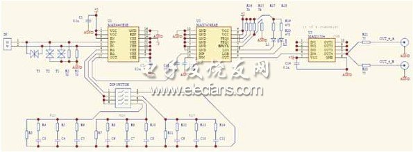
Figure 2 1200m adaptive video signal transmission scheme
The advantages of this solution are:
• Eliminate the difference in compensation effect caused by the difference in wire quality. In actual security engineering, there are many brands of network cables used by users, and the quality will be different. The compensation parameters set in the transmission equipment are in a specific material. Debugging under the network cable. Therefore, when laying another network cable in the project, the compensation effect will be different. In the Maxim scheme, since the chip MAX7474 with automatic equalization function is adopted, the difference in compensation effect caused by the difference in wire quality can be eliminated well.
• Eliminate the difference in compensation effect caused by the difference in actual installation distance in the project. The compensation parameters set in the transmission equipment are generally debugged at a specific distance, such as 600 meters. In actual security engineering, the installation distance will not be exactly 600 meters, and may be 650 meters. The compensation effect of the compensation parameters set by the DIP switches in the device will be different. In Figure 2, due to the use of automatic equalization function Chip MAX7474, which can well eliminate the difference in compensation effect caused by the difference in actual installation distance in the project.
• It is well known that the difference in compensation effect caused by the difference of resistance container components in the equalization network is known. The precision of commonly used resistors and capacitors is low. The precision of resistors is generally 1% or 5%, and the precision of capacitors is generally 10% or 20%. Therefore, even if the compensation parameters of the balanced network are debugged under the network cable with a specific installation distance and a specific material, the compensation effect of the two sets of resistance components will be different due to the dispersion of the parameters. Because the circuit of FIG. 2 adopts a chip with automatic equalization function, the difference in compensation effect caused by the difference in the parameters of the resistance container in the equalization network can be well eliminated.
Comparing Figure 3, Figure 4 and Figure 5, we can clearly see the compensation effect of this scheme on the video signal.
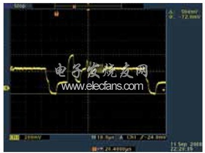
Figure 3 800 meters transmission distance (without any compensation)
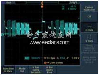
Figure 4 800 meters transmission distance (first stage MAX4445 compensation)
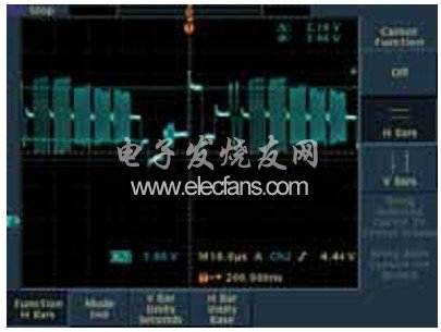
Figure 5 1200 meters transmission distance (the first stage MAX4445 and the second stage MAX7474 jointly compensate)
Conclusion The MAX7474 provides cable loss compensation for the transmission of composite video signals over unshielded twisted-pair cables. By monitoring the amplitude adjustment gain of the color video signal sync and color burst signals at the output, the cable length is adaptively balanced. When using network cable transmission, MAX7474 can completely balance the loss of 300m transmission cable, and can effectively improve the signal integrity of 600m transmission cable. The MAX7474 accepts NTSC and PAL differential video signals, including unity-gain video output drivers and adjustable back-clamp DC levels. The device also provides LOS and LOB logic output instructions.
In this solution, we use MAX4445 in conjunction with an external resistance-capacitance equalization network to fixedly compensate for specific transmission distances, and combine the features of MAX7474 automatic equalization to compensate for differences caused by network cable quality, installation distance, and dispersion of resistance device parameters. Very good It has solved the adaptive transmission of 1200 meters video signal.
The shipboard medium voltage power cables are intended for shipboard and off-shore building to transmit power.
Standards applied: IEC60092-350, IEC60092-354, IEC60092-360, IEC60228, IEC60332-1-2, IEC60332-3-22, IEC61034, IEC60754 and IEC60684-2.
Product making: factory name, type, rated voltage core.
Making: colour tape.
Medium Voltage Marine Power Cable
Different Types Of Electrical Cable,Medium Voltage Marine Power Cable,Electrical Marine Power Cables,Marine Control Power Cable
Jiangsu Jiangyang Special Cable Co,.Ltd. , https://www.jymarinecable.com