
1 Introduction
MAX9736A / B is a general-purpose class D speaker amplifier, integrated spread spectrum regulator without filtering, eliminating expensive and bulky LC filters, thereby reducing EMI and BOM costs. The wide range of single supply voltage (8 ~ 28V) allows direct battery power supply in portable applications. The excellent thousands of recovery characteristics eliminate the audible noise generated by the pseudo-overload of Class D amplifiers. The device is suitable for TV, teleconference, PC, docking station or any application that requires low cost and high efficiency amplifier. Here is a design scheme of MP3 player based on Class D audio amplifier MAX9736A / B.
2 System design structure
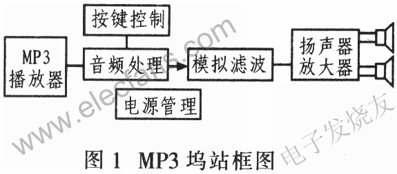
Figure 1 is a block diagram of MP3 docking station (dockingstaTIon). The system is designed to be installed in a carefully designed box and contains all electronic components and speakers. The entire system requires only one external power supply and signal source. Two 2-inch speakers are used for left and right channels, and a 5-inch speaker is used for subwoofer. One MAX9736B works in stereo mode to drive the left and right channels: the other MAX9736A works in mono mode to drive the subwoofer channel.
3 system hardware circuit design
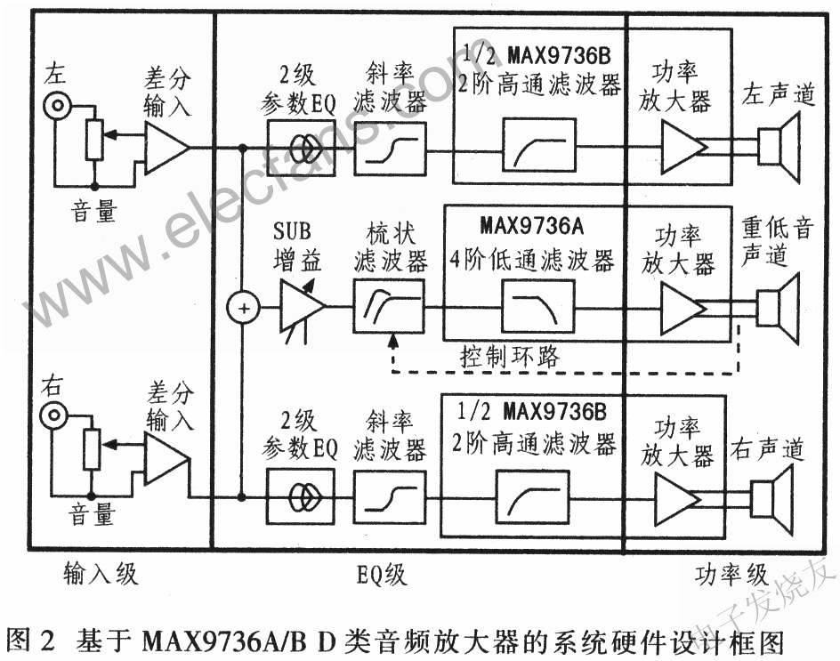
The hardware circuit design of the system has two parts of left and right channels and subwoofer channel. Each part includes input level, EQ level and power level, as shown in Figure 2.
3.1 Input level
The input level of the left / right channel and the subwoofer channel are the same. Stereo, log-tap potentiometers are used as volume controls to adjust the signal of the preamplifier. To avoid ground loop interference, the input stage uses a differential form, and the RCA input connector is not directly connected to the system ground. Use a 100Ω resistor to reduce the common-mode voltage: The MAX4234 provides a 2x gain and converts the differential signal to a single-ended output. The output of the input stage is referenced to VREF, which is the reference voltage of the power amplifier MAX9736A, which is buffered by the MAX4234.
3.2EQ level
After the input stage, the left / right channel signals enter the two-stage parametric EQ circuit, which are located near the left / right channels, respectively. Each parametric EQ uses an op amp gyrator to simulate the inductance in the LC series resonant circuit. The two access points of the series circuit realize attenuation or amplification, and these access points are realized by two capacitors. Figure 3 shows the left-channel EQ-level circuit. In the figure, capacitors C105 and C106 are the first-level parameter EQ of the left channel, and are the boost and attenuation nodes of the left channel. If only C106 is used (C105 is not connected), the resonance circuit and the series resistor R105 (10kΩ) form a voltage divider to attenuate the resonance frequency signal. On the contrary, if only C105 is used, the feedback is reduced, and the resonance frequency signal is increased. If neither capacitor is used, this part of the circuit is disabled.

The resonant frequency f0 can be calculated by equation (1):
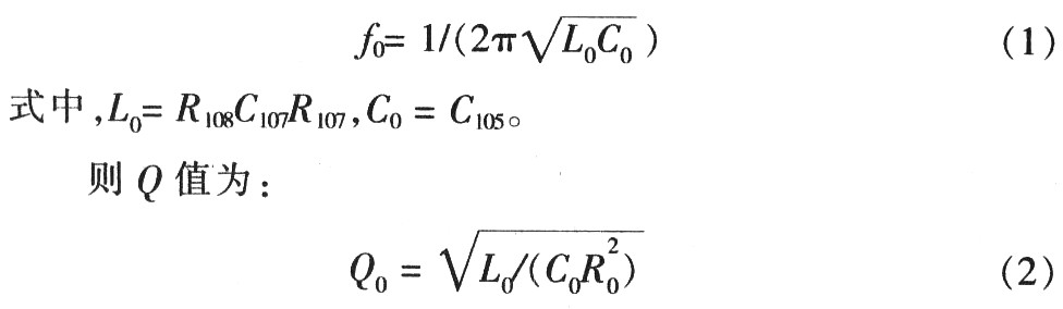
Adding a third-stage EQ circuit to achieve tilt-type filtering requires only RC components: capacitor C113 for boosting, C114 for attenuation and resistor R111.
As a stereo Class D amplifier, the MAX9736 also integrates two operational amplifiers at the input stage for general-purpose filters. The system design uses these two operational amplifiers to build a second-order high-pass filter for the left / right channels. The operational amplifier provides inverting input and output terminals, and a multi-feedback inverting filter can be built.
3.3 Power level
The system design can provide 3 channels of speaker power amplifiers. The MAX9736B is used in stereo mode to drive left and right channel speakers, and can provide 2 × 11W power for 4Ω speakers. The MAX9736A is configured in mono mode for the third channel and drives the subwoofer amplifier.
In mono mode, the two Class-D amplifier outputs of the MAX9736A are connected in parallel to provide greater output power. The mono subwoofer provides 30W power (VDD = 19V) for 4Ω speakers. The input level of the subwoofer channel is the same as the input level of the left / right channel. After the input level, the left / right channel signals are superimposed through MAX4234 (UA) and (UB) to provide the drive for the mono subwoofer. R303 sets the gain of the subwoofer in the superimposed amplifier, as shown in Figure 4.
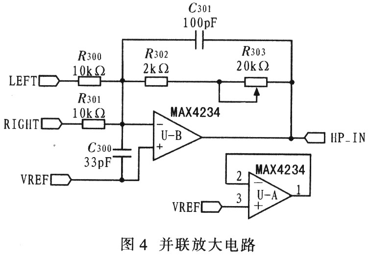
Figure 5 shows the subwoofer circuit. In order to extend the flat frequency response characteristics to very low frequencies, the system provides a 6th order filter circuit for the subwoofer. On the basis of the 4th-order high-pass frequency response of the open-hole speaker, a 2nd-order active high-pass filter is added. The MAX4234 provides in-phase Sallen-Key 2nd-order high-pass filtering for the subwoofer.
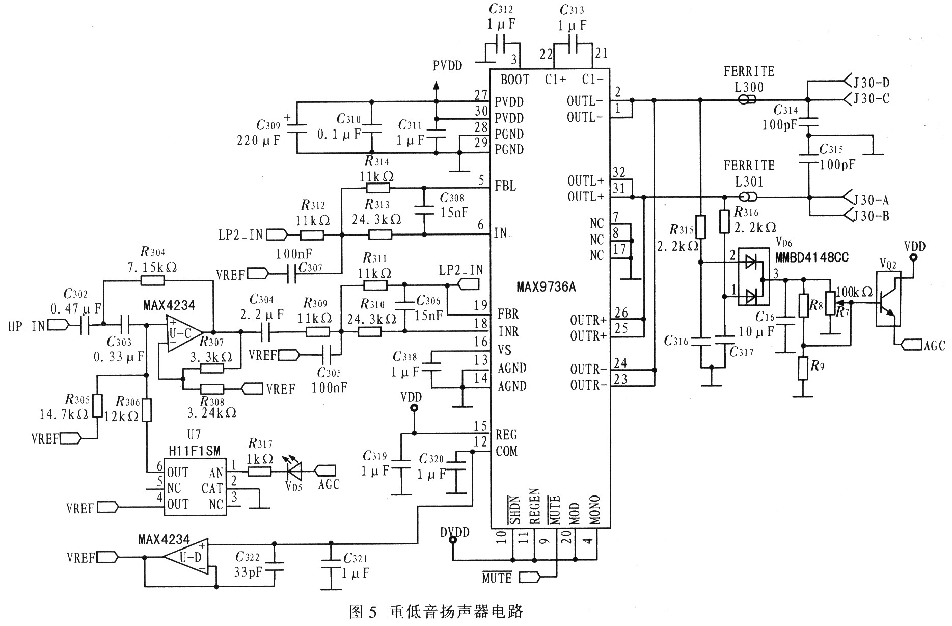
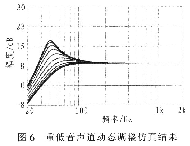
The system requires a high Q value, which is increased by 13dB at the frequency of 40Hz. In order to avoid overloading of speakers and amplifiers, the Sallen-Key filter is configured to realize sliding high-pass filtering; the filter is dynamically adjusted when the amplifier output reaches the maximum value. The input resistance R305 can be automatically reduced (using optocoupler FET, U7), so that the filter Q value drops below 0.5, that is, there is no improvement. The output peak voltage of the subwoofer amplifier U2 controls the input signal of the optocoupler FET. VD6 and C16 form a peak detector, which can quickly detect the output peak voltage. The threshold of the peak detector can be adjusted or fixed, depending on whether R7 and R8 / R9 are installed. LEDVD6 will be opened when the control circuit is working. The two operational amplifiers inside the MAX9736A are configured as a fourth-order subwoofer low-pass filter, which is used as a subsequent filter for the left / right channel high-pass filter. Figure 6 shows the simulation results of dynamic adjustment of the subwoofer channel. After the subwoofer signal reaches its threshold, the Q value of the high-pass filter decreases and the cutoff frequency increases.
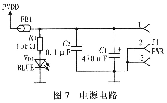
JI power input connector for standard laptop coaxial plug. The average output voltage of a typical notebook computer power supply is about 19V, which is suitable for the power supply of the docking station system. After filtering through C1 and C2, the voltage is marked as PVDD, and the VD1 blue light is lit after the power is connected, as shown in FIG. 7.
A simple reset circuit MAX809SEUR + is used to provide a mute signal to the amplifier during power-up and power-down to avoid transient noise during the establishment of the input circuit signal. The mute control threshold is set at about 10V through two series resistor dividers (10kΩ and 4.22kΩ). The MAX9736 uses patented filter-less modulation technology and does not require an external large-size inductor filter. Only simple ferrite beads are needed at the output.
4 speakers and chassis
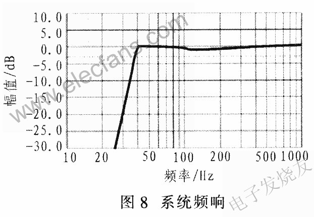
The subwoofer uses Tymphany's 5-inch diameter speaker, model 830945, nominal impedance 4Ω, resonance frequency 47.4Hz. The left / right channel uses a 2-inch speaker, Tymphany830970, a nominal impedance of 4Ω, and a resonance frequency of 147.5Hz. The f3 as low as 35Hz is used in voice systems and uses a 6th-order filter circuit, including a 2nd-order high-pass active filter. The entire system is placed in a chassis, including three speakers, adjustment ports and PCB board. The subwoofer is installed with the opening down, the volume of the chassis is about 3.791mm3, and it is tuned at 54Hz. The size of the case is about 355mm ~ 180mm × 120mm. The speaker filter equalization is designed as a 4th order Linkwitz-Riley filter of 250Hz; while the satellite speaker equalization includes the parametric EQ of f = 500Hz, gain = + 6dB, Q = 0.5 and the slope type of f3 = 3.8kHz, gain = + 5.8dB The filter, Figure 8 shows the system frequency response. The simulation of the frequency response characteristics of the entire system shows that the maximum flatness extends to 40 Hz accordingly. Here the speaker housing is recommended to use materials with higher cost performance, such as wooden materials, fiberboard (MDF), engineering plastics (ABS), etc.
5 Conclusion
The system design uses 12 to 20V DC power supply, uses small speakers to provide higher SPL output, high-efficiency class D design, active EQ, including dynamic bass equalization, and cost-effective drivers provide excellent sound quality.
Introduction of EMI Filter In Medical Devices
Rated currents: 0.5 to 300A
Various types of connections: pin, IEC inlet, wire, solder lug, thread, terminal block, etc.
Custom specific versions available on request
Features of Medical Device FiltersExcellent common and differential mode attenuation effect, guarantees the accuracy and reliability of medical equipment;
Very low leakage current, fully comply with the safety requirement of medical devices.
Items with IEC inlet or pin connection available, compact structure, easy to install, high cost performance;
Three-phase versions are suitable for high power medical devices, which are safe and effective.

Ac Noise Filter,EMI Filter In Medical Devices,EMI Filter For Medical Appliance,Medical Device Filters
Jinan Filtemc Electronic Equipment Co., Ltd. , https://www.chinaemifilter.com