
When developing a permanent magnet synchronous motor control system with DSP as the core, it is necessary to observe various variables in the drive system in time, and also control some programs and modify specific parameters. In actual operation, DSP cannot be controlled by an external port, and it is necessary to use the serial communication module that comes with DSP to solve this problem. The entire monitoring system is formed by a host computer and a motor control system with DSP as the core. The Pc machine changes the torque and flux setting in the DSP program through the serial port and adjusts the PI parameters. , And collect relevant data and feed it back to PC for analysis, processing, display and storage. This article takes DSP to control permanent magnet synchronous motor as an example, introduces the realization of serial communication in the whole control system.
1 Permanent magnet synchronous motor control system
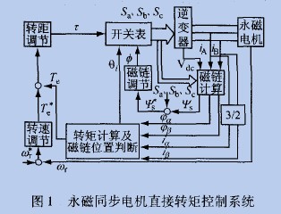
The block diagram of the permanent magnet synchronous motor control system is shown in Figure 1. It uses the direct torque control method, which is a high-performance control strategy for AC motors proposed in the 1980s. This control system is a double closed-loop control system of speed and torque. The system uses voltage and current sensors to detect the DC bus voltage Vdc. And the stator two-phase currents i and i, through coordinate transformation, convert the voltage and current variables in the three-phase stator coordinate system into two-phase components in the α-β stationary stator coordinate system. The actual values ​​of the stator flux and torque obtained from the flux linkage and torque observer are used as feedback values, and compared with the given values ​​of the flux linkage and torque. The resulting error signal passes through the hysteresis loop of the flux linkage and torque regulator After the control unit obtains the control signals 0 and 1, and then comprehensively considers the area where the current stator flux linkage is located, the appropriate voltage space vector is selected to control the rotation speed and direction of the stator flux linkage, and torque regulation can be achieved directly and quickly.
If the testers can observe and adjust the control parameters such as torque, flux, voltage, and current in time, the development efficiency of the motor control system will be greatly improved.
2 Realization of serial communication
The realization of serial communication between PC and DSP includes three parts, namely hardware design, upper computer programming and lower computer programming.
2.1 Serial communication hardware design
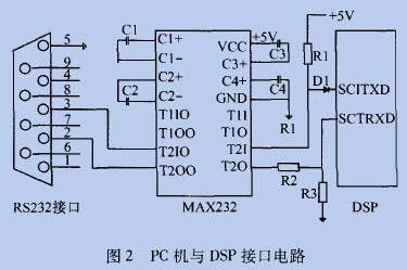
According to the actual needs of this test platform, RS-232 is used to realize the data transmission between PC and DSP. Now RS. The 232 communication port is a necessary configuration on each computer. It usually contains two ports, COM1 and COM2, so it is easy to connect the upper computer and the lower computer to realize the monitoring and control of the production site by the computer. Figure 2 is the TMS320LF2407 serial communication connection 1: 1 circuit [1]. This circuit adopts the driver chip MAX232 conforming to the RS-232 standard for serial communication. The MAX232 chip has low power consumption, high integration, +5 V power supply, and 2 receiving and transmitting channels. Since the TMS320LF2407 uses +3.3 V power supply, the 1TI1L level of 5 V needs to be converted to 3.3 V high level. The entire interface circuit is simple and highly reliable.
2.2 Computer programming
Delphi is an object-oriented visual programming tool. It has a powerful integrated development environment and a very fast compiler. It also has the powerful functions of Visual C ++ and the features of VB that are easy to learn and use. By installing the MSComm control, serial communication can be easily achieved in the Delphi environment [2]. MSComm provides two methods for dealing with communication problems: one is the event-driven method, and the other is the query method. This system selects the event-driven method, which has timely response and high reliability. As long as you understand the properties of using MSComm and the usage of events, you can implement operations on the serial port.
Its main attributes are:
(1) eommport attribute, used to set and return the serial port number of the connection;
(2) setTIngs attribute, set and return serial port baud rate, parity, data bit, stop bit parameters in character form;
(3) po ~ open attribute, used to set or return the status of the communication connection port;
(4) The input attribute is used to return and delete characters from the input buffer;
(5) The output attribute is used to input the data to be sent into the transmission buffer;
(6) inputlen attribute, used to specify the length or number of bytes of the string read by the serial terminal I: I;
(7) handshaking attribute, used to specify the handshake agreement between the two parties of communication;
(8) rthreshold attribute, used to set or return the number of bytes that caused the receive event;
(9) sthreshold attribute, used to set and return the minimum number of characters allowed in the transmission buffer;
(10) Commevent attribute, oncomm event will be generated when communication error or event occurs;
(11) inbufercount attribute, used to receive the number of characters in the buffer;
(12) The inputmode attribute is used to set or return the input attribute to retrieve the type of data.
In the program design, MSComm must be initialized first. You can double-click the MSComm control setting, or you can modify it in the program.
This system has designed communication protocol according to the need.
(1) Frames are divided into two categories, namely control frames and data frames. The control frame is the control command sent by the upper computer, and the data frame is the real-time data of the upper and lower computers.
(2) The control frame in the communication between the upper computer and the lower computer has a format of one byte, which is defined as follows: AA is the lower computer to send data; AB is the lower computer to receive data; AC is the lower computer to stop sending
(3) The data frame is two bytes, and the data range is 0 to 65535, which meets the data requirements.
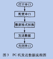
For example, set the motor flux linkage to 200, the communication command consists of 4 bytes, and the data format is AB0400C8. Among them: AB is the control frame, 04 represents the magnetic chain, 00C8 is the data frame. Each byte contains 1 start bit, 1 stop bit, and 8 data bits, which are hidden in the underlying program. In practical applications, users only need to set the flux linkage value 200 on the communication interface This command can be realized by clicking the "n send" button. Figure 3 is the flow chart of PC sending data.
Protective Suit,Protective Personal Suit,Medical Isolation Gown,Disposable Isolation Gown
Ningbo Anbo United Electric Appliance Co.,ltd , https://www.airfryerfactory.com