
In recent years, portable music players have shined and become popular. There are many reasons for this, such as the massive amount of compressed music content, the cost of data storage is declining, the operation is simple and the online music content of different popular elements is easily accessed. Consumers are increasingly picky about next-generation music players, expecting longer audio playback times and a richer listening experience.
This resulted in the Cortex-M series, which is a new generation of ARM low-cost microprocessors designed with low power consumption. The Cortex-M3 core and the recently released Cortex-M4 core are based on the three-stage pipeline of the Harvard architecture and use the Thumb-2 instruction set architecture (ISA), with lower memory requirements. But can these MCUs be competent for audio processing tasks? Can they create a better listening experience and meet people's expectations?
In order to analyze whether these processors are suitable for processing audio, first of all, we take MP3 decoders and equalizers as an example to roughly understand the implementation of audio processing modules commonly used in audio components such as audio decoders and post-processing, and then implement the processing of these modules according to high efficiency. According to the requirements of the device instruction set architecture, the modules are classified.
We focus on the advantages of the Cortex-M3 and Cortex-M4 cores in audio processing from the perspective of the instruction set. To this end, we first discuss some module code examples of different audio components, then analyze the unique advantages of these processors in terms of loops and instructions, and finally, show the typical performance indicators of popular audio codecs and audio post-processing components to support these The audio capabilities of the processor core.
Function block of audio processing module
In order to analyze the requirements of the audio processor, let us start with the functional blocks involved in the audio processing module, namely the audio codec and the audio post-processing component. The modules in the block diagram of this section are color-coded into 3 different categories. Green indicates a multiply-add (MAC) dense module, red indicates a mixed MAC and control code module, and blue indicates a control code module.
Audio codec
The Internet provides a large amount of compressed audio data, which inevitably requires music players to support a variety of popular audio decoders. The processing function of the audio encoder involves a series of functional blocks, which we will review next.
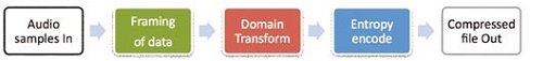
Figure 1: Block diagram of a typical audio encoder.
Audio encoder: The purpose of the audio codec is to achieve audio data compression while striving to obtain fidelity sound quality under the constraints of a given bit rate. A typical encoder is shown in Figure 1. Generally speaking, the audio encoder uses the following three steps to complete the compression: First, adjust the audio data through data filtering. Then, the audio data is framed by windowing and overlapping, waiting for further processing; then, this data is transformed into the frequency domain to eliminate redundancy in the time domain. Using psychoacoustic principles, calculate the amount of quantization noise that may be introduced and inaudible; finally, the data is quantified and further lossless compression is achieved through entropy coding. This encoded data is tightly packed into a bit stream. Although the compression achieved is somewhat lossy, it is difficult for the hearing to distinguish nuances.
Audio decoder: Reverse the above process of the audio encoder, that is, the principle that the audio decoder restores audio data from the bit stream. The MP3 decoder is taken as an example for discussion here, and the high-level module decomposition is shown in Figure 2. The block diagram takes compressed audio in MP3 file format as input and outputs uncompressed audio in PCM format.
These modules are named after functions and represent the operations they perform

Figure 2: Block diagram of the MP3 decoder.
"Bit Stream Demux" module parses MP3 bit stream
"Entropy & Inv Q" module performs Huffman decoding and inverse quantization
The "IMDCT" module reversely modifies this data by discrete cosine transform
"Overlap and Add" module performs windowing, overlap and addition operations
"Synthesis Filter Bank" reconstructs time domain samples from filter bank domain data
Piezoelectric Ceramic Ring
Applications: ultrasonic vibration tranducer for inkjet printer
Vibration mechanism of inkjet printer:
Generally, it is composed of piezoelectric ceramics and driving rods. By high-frequency electric excitation, piezo ceramics produce high-frequency ultrasonic vibration (above 60 kHz or higher), which is transmitted to the driving rod and generates high-frequency micro-displacement (back and forth expansion) at its front end.
Piezo ceramics components features :
1. High vibration amplitude and can withstand higher power.
2. The product has high reliability, strong maintainability, and is not easy to break down or off-line.
3. The frequency can be adjusted in a wide range, generally within the range of 10KHz.
Yuhai support all the new developping transducer, Welcome the customized elements inquiry.
The present Piezoelectric Elements For Inkjet Piezo Transducer is following :
Piezo rings OD4*ID2*2.5mm price USD1.20/pc, 2000pcs
Material: PBaS-4
Fr.: 694 KHz ±5KHz
K33: ≥0.55
Tg loss <0.5%
Ct 60pF ±12.5%
Piezo rings OD4*ID2*2.5mm price USD1.20/pc, 2000pcs
Material: PSnN-5
Fr.: 626KHz ±5KHz
K33: ≥0.57
Tg loss < 2%
Ct 53pF ±12.5%
Piezo rings OD6*ID2.5*2mm price USD1.50/pc, 2000pcs
Material: PZT-41
Fr.: 785 KHz ±5KHz
K33: >0.53
Tg loss < 0.5%
Ct 107 pF ±12.5%
Piezo Rod OD3*7mm price USD1.20/pc, 2000pcs
Material: PLiS-51
Fr.: 192 KHz ± 3KHz
K33: >0.62
Tg loss < 2%
Ct 18.7 pF ±12.5%
Piezoelectric Elements For Inkjet Piezo Transducer
Inkjet Piezo Transducer,Piezoelectric Vibration Tranducer,Piezoelectric Rings,Piezoelectric Elements For Inkjet Piezo Transducer
Zibo Yuhai Electronic Ceramic Co., Ltd. , https://www.yhpiezo.com