
At present, the most popular handheld CPUs are MIPS series, SuperH series, DragonBall series and ARM series. In the operating system field, except for some Linux and self-developed operating systems, most products use Palm OS, Windows CE and EPOC operating systems.
This article refers to the address: http://
In order to occupy a place in the main application field of the embedded system of handheld computers, Tsinghua University Automation Department and Shenzhen Xianglong Company decided to develop a handheld computer with national independent intellectual property rights. This requires the selection and development of its own hardware platform; at the same time, it must develop its own embedded Linux operating system; on the hardware platform and operating system, develop various specific applications to meet the needs of specific users. The design of the liquid crystal display described in this article is an important part of the overall system design.
1 hardware circuit composition
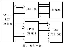
The hardware circuit of the handheld computer liquid crystal display based on SAlll0 microprocessor is shown as in Fig. 1. Mainly composed of three parts: LCD controller, ASIC chip CPLD and LCD LCD.
2 SAlll0 LCD controller
The LCD controller is integrated inside the SAlll0 chip. The controller has three display types:
- Passive color mode: supports 3375 colors, allowing 256 colors to be displayed per frame;
- Active color mode: supports up to 65,536 colors (16 bits);
- Passive black and white mode: Supports 15 levels of gray.
The LCD controller supports display screens up to 1024 x 1024 pixels. However, in the frame memory, the size of the display screen that the LCD can drive is limited due to the bus width of the memory and the size of the pixel encoded data. The LCD controller also supports single and dual display. The pixel-encoded data is stored in an external memory, and the LCD's dual-channel DMA controller can load the data into a 5-cell (32-bit long) queue buffer, as appropriate. One channel of the DMA controller is for single screen display and the other is for dual screen display.
In the frame memory, pixel encoded data is stored. The LCD controller uses it as a pointer to index a 256-unit 12-bit wide palette. The black and white palette is 4 bits wide and the color palette is 12 bits wide. The pixel encoded data (4 bits) from the frame memory addresses the top 16 cells of the black and white palette; the 8-bit pixel encoded data can access any of the 256 cells in the palette. In passive color 12-bit pixel mode, color pixel data bypasses the color palette and is sent directly to: the dithering logic of the LCD. In active color 16-bit pixel mode, color pixel data not only bypasses the color palette, but also bypasses the LCD's jitter logic and sends it directly to the LCD's data pins. Once a palette unit is selected for 4-bit or 8-bit pixel encoded data, the encoded value in this unit is transferred to the dithering logic. The dithering logic uses a space-based and time-base algorithm to generate pixel data that is output to the screen. The dithering logic causes each pixel to turn off at each frame at a different rate, producing 15 levels of grayscale for the black and white screen, and 15 levels of color for each of the red, green, and blue primary colors of the color screen. Degrees, for a total of 3,375 colors (256 colors per frame). The output data from the dithering logic is placed in a 9-cell pin data queue buffer before being output to the LCD pin and the pixel clock to drive the display.
The LCD controller can be programmed as a 4-bit, 8-bit or 16-bit pixel data pin, depending on the type of display used. A single-screen black-and-white display can use either 4-bit or 8-bit data pins to output 4-bit or 8-bit pixels per pixel clock cycle. A single-screen color display can use an 8-bit data pin to output 2 to 2/3 bits of pixels (8 pins / 3 colors per pixel) per pixel clock cycle. The LCD controller also supports dual display. The dual display causes the LCD controller data lines to be divided into two groups, one driving the upper half screen and the other driving the lower half screen.
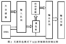
In this scenario, a passive color mode is selected. In this mode, the control process of the SAlll0 LCD controller is shown in Figure 2.
CPLD PZ3128 is a dedicated integrated chip from Philips. Due to the wide variety of liquid crystal displays of handheld devices, the inconsistencies of the standards of various manufacturers make the LCD controller of SAlll0 and SHARP's 3.9-inch TFT active color liquid crystal display unable to match in data format and display timing. Therefore, the CPLD PZ3128 can be programmed to map data interfaces of different data formats and configure dedicated ASIC chips for different types of LCD screens.
The SAlll0 LCD controller consists of the following pins:
- LDD[0~7]: 7-bit data line for 4-bit and 8-bit display modes, and also the lower 8 bits of 16-bit TFT mode;
- GPIO[2~9]: When the liquid crystal module used is 16-bit TFF mode, it constitutes the upper 8 bits of the data line;
- l_PCLK: Pixel clock, used to send data of each point to the shift register;
- l_LCLK: Line clock, used to indicate that a row of data has been transferred from the shift register to the display driver chip, and the row pointer is incremented by one. In the 16-bit TFT mode, it is a horizontal sync signal;
- l_FCLK: Frame clock, used to indicate the start of a frame of image, while placing the line pointer on the first line of the display. In the 16-bit TFT mode, it is a vertical sync signal;
- l_BIAS: In the 16-bit TFT mode, the output enable signal is used to indicate that the data signal is latched to the pin under the synchronization of the clock signal.
In order to display a frame of image, the SAlll0 LCD controller first opens up a buffer in the RAM as a frame buffer (FRAME BUFFER). Save the image data to be displayed, then let the LCD controller's DMA address register point to the start address of FRAME BUFFER, and read the data in FRAME BUFFER to the input first-in first-out queue (1NPUT FIFO). Since the 16-bit mode is used in this design, there is no need to decode the data in the frame buffer, so the LCD controller does not process the data directly to the output first in first out queue (OUTPUT FIFO). The OUTPUT FIFO then sends the data to the CPLD through the pin to drive the LCD display. Since SAlll0's LCD controller has its own independent dual-channel DMA and high-performance SDRAM, it can meet the display bandwidth requirements. 3 LCD module
As prices have fallen, liquid crystal displays have been widely used in a variety of handheld devices due to low power consumption, no radiation, and light weight. In particular, TFY-LCD has the advantages of high resolution, wide viewing angle, high contrast, etc., and is widely used in high-end handheld computers.
The SAlll0, which is a SOC chip, has an LCD controller in itself, and supports a variety of monochrome and color LCDs in 4, 8, 12, and 16-bit formats, which brings great convenience to developers. According to the user's requirements to consider the actual display effect, this program selected SHARP 3.9-inch TFT active color liquid crystal display, the specific model is: LQ039Q2DS54.
The display module is a color reflective and active matrix LCD module, which is composed of a TFT color LCD screen, a driving chip, an FPC lead, a front light, a touch screen and a back sealing plate. The dot matrix format is 320 × 3 × 240, which can display graphics and text, and can display up to 262,144 colors.
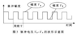
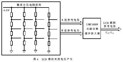
The liquid crystal module requires 10 levels of standard analog pulse voltages V0 to V9 for reference in the grayscale display inside the LCD module. These voltages directly affect the accuracy of the color and grayscale displayed on the LCD, and their numerical requirements are highly accurate. At the same time, they are pulse signals that require steep edges to ensure clear display points. 3 is a waveform diagram of V0 to V9, and the amplitude parameters of V0 to V9 are as shown in Table 1.
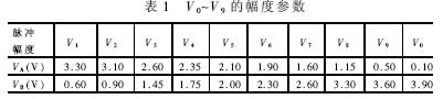
The voltage signal is generated in Table 1. The array is formed by high-precision resistors. The reference voltage is generated by the resistor divider method. Then, the switch is switched at high speed according to the frame frequency displayed by the LCD. The required standard can be obtained at the output. Analog pulse voltage. Among them, the second selection switch uses LMC6009, and the part of the circuit is shown in Figure 4.
Like many TFTs, the LQ039Q2DS54 uses 18-bit encoding for each pixel. Each of the primary colors of red, green, and blue is 6 bits, that is, RGB666. However, the LCD controller of SAlll0 supports the 16-bit mode, so the lowest bits of red and blue must be grounded to form a 5-bit red, 6-bit green, and 5-bit blue RGB565 format. The resulting color difference is very small.
4 touch screen
Typically, touch screens for handheld devices are typically integrated with the LCD screen and attached to the surface of the LCD. The SHARP 3.9-inch TFT LCD (LQ039Q2DS54) is equipped with a resistive touch screen. The basic structure is shown in Figure 5. It is divided into two upper and lower plates of X and Y.
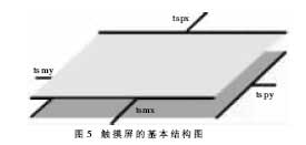
The position and pressure of the contact points can be measured via a resistive touch screen. When you need to test the X coordinate, first apply a bias voltage to both ends of the X plate, and then test one or all of tspy, tsmy. They correspond to the sliding end of the potentiometer and the measured voltage value is proportional to the X coordinate of the contact. The Y coordinate test is the same, except that the X plate and the Y plate are interchangeable. The characteristic parameters of the SHARP 3.9-inch TFT LCD (LQ039Q2DS54) surface-mounted resistive touch screen are as follows:
- Input voltage: 5V;
- Resistance between X1 and X2: 320Ω;
- Resistance between Y1 and Y2: 580Ω;
- Line linearity in the X or Y direction: 1.5%;
- Insulation resistance is greater than: 20MΩ;
- The minimum pressure that can be detected: 24g.
The UCBl300 from Philips used in this design can be used not only as a MODEM and audio analog front-end chip, but also integrated with a touch screen controller inside, which can be used in a handheld system. The function of the touch screen controller includes: applying a bias voltage between the two plates of the touch screen, generating an interrupt signal when there is a click action; and simultaneously digitally quantifying the analog voltage signals in the X and Y directions at the click to obtain a click position. The data is stored in the internal registers; it is read into the microprocessor through the MCP interface. The features related to the UCBl300 and the touch screen controller are:
(1) The complete four-wire resistive (pressure-sensitive) touch screen interface circuit, which is connected to the four signal lines tspx, tsmx, tspy and tsmy of the touch screen, can measure the position, pressure and plate resistance.
(2) 10-bit continuous approximation ADC with internal tracking and holding circuit and analog multiplexer for reading of touch screen contact data and monitoring of 4 analog voltages of external circuit, wherein 4 external voltage monitoring for external circuit For power management.
(3) Internal reference voltage source to provide reference voltage and virtual ground reference for 10-bit ADC. This is independent of supply voltage and temperature variations.
(4) 4-wire high-speed serial interface data bus, realizes synchronous serial communication with MCP of main processor SAlll0, and has strict data frame definition.
(5) The various working modes of the touch screen are set by the internal control register of UCBl300, and these control registers are read and written by SAlll0 through the MCP synchronous serial port.
(6) Because of the close coupling between the touch screen and the LCD, large spikes from the LCD screen can affect the operation of the touch screen. Therefore, the touch screen controller has four low-pass filters inside to reduce high frequency interference from the LCD.
Although there are many PDAs and PDA products in the domestic market, some domestic brands are also very popular. However, in product design and manufacturing, they rely on OEMs from Taiwan and other manufacturers to truly research and develop hardware platforms. Almost zero. Therefore, the successful development of the handheld computer hardware platform system in this project, especially the prototype based on Intel StrongARM SAlll0 high-performance CPU, is still in the leading position in China, and provides the same group of personnel to develop embedded operating systems and various applications. Hardware environment.
277V CC/CV LED Driver,LED Driver Circuit ,LED Power Driver,LED Transformer
LED Power Supply Co., Ltd. , http://www.nbleddriver.com