
1 Introduction
This article refers to the address: http://
Calibration refers to adjusting, optimizing and determining the control parameters of each ECU (such as engine, AT and other subsystem ECUs) on the vehicle according to various performance requirements (such as power, economy, emissions and auxiliary functions). Control algorithm. The calibration system is mainly composed of the upper computer and the lower ECU. Therefore, the communication mode between the upper computer and the lower ECU plays a crucial role in the performance of the entire calibration system. At present, the general calibration system uses a point-to-point communication method based on serial port. This communication method is easy to implement, but there are defects such as slow communication speed and low reliability. Here we use the communication method of CAN bus. Compared with serial communication, the communication method based on CAN bus has the advantages of reliable communication [1], fast transmission speed and online programming.
2 overall design
CAN communication can be regarded as an I/O character stream device [3] of the system, which can realize the necessary device independence of the driver while completing the ordinary transceiver function. That is, the driver should encapsulate all the hardware features of the system, providing a hardware-independent, universal programming interface for the application using the device. The application layer programmer can smoothly control the device without knowing the principle of the device. , through the device to achieve reliable data exchange. In addition, for the real-time requirements of CAN communication and embedded systems, the driver requires reliable data transmission and reception, short delay, short system time, short execution time, short shutdown time, and error in sending and receiving errors and abnormal situations. , report to the application. In addition, the driver needs to monitor the operating status of the CAN controller, reset the CAN module and report to the system in the event of a fatal error and disconnection from the bus.
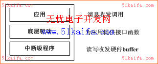
Figure 1 driver overall structure
Based on the above requirements analysis, combined with the drive scheme of the I/O serial device and the bus requirements of the CAN in other OSs, the overall driver structure is designed as shown in Fig. 1.
3 CAN driver module implementation
Based on the above overall design framework, first define a CAN class to encapsulate the data structure and functions in CAN communication. The bottom layer is the interrupt level program. The interrupt handler wakes up the driver every time the CAN controller finishes sending and receiving. Work in one step. In the interrupt handler, it is determined according to different interrupt vectors whether a transmission completion interrupt or a completion interrupt is currently occurring, and the corresponding work is completed. The middle layer is the underlying driver. The underlying driver mainly completes the configuration and status detection of the CAN port by reading and writing to the CAN controller registers, and provides an interface for device-independent software and user programs. In this layer, a ring buffer structure must be established. The buffer consists of a receive ring buffer and a transmit ring buffer. The data structure is shown in the following code. For each ring buffer, design A save pointer points to the next save address to be stored in CANMsg, a read pointer points to the address of the next (most old) CANMsg to be fetched in the buffer, and a counter records how many CANMs are in the current buffer. Take out, a semaphore used to exchange messages with the application. The receive ring buffer is used to buffer the received bus message and wait for the application to process. The send ring buffer is used to buffer the message sent by the application and wait for the interrupt program to be processed.
Typedef struct{ // data structure of the ring buffer
INT16U RingBufRxCtr; //Receive counter
OS_EVENT *RingBufRxSem; //Semaphore
CAN_msg *RingBufRxInPtr; / / receive buffer pointer
CAN_msg *RingBufRxOutPtr; //Read pointer of the receive buffer
CAN_msg RingBufRx[CAN_RX_BUF_SIZE]; //Message storage for the receive buffer
INT16U RingBufTxCtr; //Send counter
OS_EVENT *RingBufTxSem;
CAN_msg *RingBufTxInPtr; //Save buffer pointer
CAN_msg *RingBufTxOutPtr; //Read pointer of the send buffer
CAN_msg RingBufTx[CAN_TX_BUF_SIZE]; //Message storage for the send buffer
}CAN_RING_BUF;
3.1 The underlying driver
The underlying driver module provides an interface function for our application to receive and send messages.
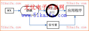
Figure 2 CAN Receive Message
When receiving a message [3], as shown in Figure 2, the application waits at the semaphore; after receiving a message, the ISR reads the message from the serial port and stores it in the ring buffer. The ISR then sends a semaphore to inform the task waiting for the serial data that a message has been received. After waiting for the semaphore to receive the semaphore, it enters the ready state and is ready to be activated by the OS scheduler. When the kernel schedules the task to run, the task takes the message out of the ring buffer and completes the process of receiving the message.
Void CAN_GetMsg(CAN_msg *msg){
INT8U oserr;
OS_CPU_SR cpu_sr;
CAN_RING_BUF *pbuf;
Pbuf = &ringbuf;
OSSemPend(pbuf->RingBufRxSem,0,&oserr); //Wait for semaphores
OS_ENTER_CRITICAL();//Off interrupt
Pbuf->RingBufRxCtr--;//Receive counter minus 1
CopyMsg(pbuf->RingBufRxOutPtr++, msg); //Retrieve the semaphore from the ring buffer
If(pbuf->RingBufRxOutPtr==&pbuf->RingBufRx[CAN_RX_BUF_SIZE]) {pbuf->RingBufRxOutPtr= &pbuf->RingBufRx[0];
/ / If the read pointer of the ring buffer reaches the end of the buffer, change it to the first address of the buffer }
OS_EXIT_CRITICAL(); //Open interrupt, allow CPU to respond to interrupt }
Sending a CAN message is similar to accepting a message. The background process stores the message frame to be sent in the send ring buffer. When the CAN port is ready to send a frame message, an interrupt is generated, the CAN message is taken out of the buffer and output by the ISR [4]. But there is a problem: the CAN port can only generate an interrupt when the last data is sent. The moment of this interrupt is inconsistent with the time we need to perform the interrupt task. The solution to this problem is to disable the sender interrupt enable until the message needs to be sent again. When the system starts, it is forbidden to send an interrupt and send a start message frame. At this time, the transmit completion interrupt flag bit has been set, but since the transmit interrupt enable bit is low, the interrupt cannot be generated and the system continues to execute. When the first message needs to be sent, the message is placed in the send ring buffer, and then the send interrupt is run. At this time, the last time the message is sent, the interrupt is generated and the message is sent. At the end of the sending of the message, if there is other data in the ring buffer to be sent, the interrupt source is cleared, and the message is sent to complete the interrupt to send the next message. If no other data needs to be sent, the transmission is directly prohibited. Interrupt, the interrupt generated when the message is sent is retained until the next time a message needs to be sent.
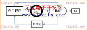
Figure 3 CAN sends a message
The method of sending a message is shown in Figure 3. When the transmit ring buffer is full, the semaphore is used as an indication to suspend the send task. The task waits for a semaphore when sending a message. If the ring buffer is not full, the task continues to store the message to be sent to the ring buffer. If the stored message is the first byte of the buffer, the transmit interrupt is enabled and the interrupt routine is ready to start. The CAN Transmit ISR takes the oldest message from the ring buffer and sends a semaphore to inform the sending task that the ring buffer has room to receive another message, and then the ISR sends the message from the bus. The implementation code is as follows:
Void CAN_PutMsg(CAN_msg *msg) {
INT8U oserr;
OS_CPU_SR cpu_sr;
CAN_RING_BUF *pbuf;
Pbuf = &ringbuf;
OSSemPend(pbuf->RingBufTxSem, 0, &oserr); //Wait for semaphores
OS_ENTER_CRITICAL();//Off interrupt
Pbuf->RingBufTxCtr++; //Send counter plus 1
CopyMsg(msg, pbuf->RingBufTxInPtr++); // put the message into the ring buffer
If(pbuf->RingBufTxInPtr==&pbuf->RingBufTx[CAN_TX_BUF_SIZE]) {pbuf->RingBufTxInPtr=&pbuf->RingBufTx[0];
}
If (pbuf->RingBufTxCtr==1) {
CAN_TxIntEn();// is the first message of the ring buffer, open transmission interrupt
}
OS_EXIT_CRITICAL();
}
3.2 Interrupt Service Procedure
According to the software structure of sending and receiving messages, the CAN receiving interrupt is required to be turned on during CAN initialization, and the sending interrupt is only turned on after the first message is in the sending buffer, so Here we design two interface functions, CAN.TxIntEn() and CAN.TxIntDis(), which will send the masking position 1 (allowing the transmission completion interrupt) and setting 0 (disabling the transmission completion interrupt).
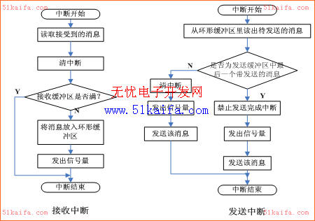
Figure 4 Flow chart of sending and receiving interrupt program
The core of the interrupt level program is CANRX_ISR() and CANTX_ISR(), which are the interrupt levels set by the interrupt setting registers of the module at initialization. As shown in FIG. 4, if the interrupt is received, the interrupt source is cleared, and the received message is placed in the receive buffer; the message is stored in the receive buffer and stored at the address pointed by the pointer, and the pointer is moved downward. The receive buffer counter is incremented by 1, and a semaphore is sent to notify the application that a new message has been received. If a task is waiting for a new message on the CAN, the task enters the ready state and waits for the OS to schedule. If the transmission is completed, the message to be sent of the transmission buffer is read out; the oldest message is read from the one with the highest priority (the message pointed by the buffer fetch pointer), and the buffer counter is sent. Decrease by 1, the semaphore informs the application that a message has been sent, and reports the status of the current send buffer; it should also determine if it is the last message to be sent, and if not, clear the interrupt source and send the message to the bus. If it is the last one, it is forbidden to send the message after the completion interrupt is sent, and the transmission completion interrupt is reserved and allowed to be generated when the application sends the message next time.
3.3 Application
The application of the driver, as shown in the following code, is uCOS-II. First, define a CAN message object (msg) and a ring buffer data structure (CANRingBuf). In the main program, call Ringbuf_Init after initializing the OS. The () function initializes the ring buffer and then calls the CAN_Init() function to initialize the CAN port. After starting the OS, the user can call CAN_PutMsg (CAN_msg *msg) and CAN_GetMsg (CAN_msg *msg) to send and receive bus messages in any task.
CAN_msg msg;
CAN_RING_BUF CANRingBuf;
Void main(void) {
OSInit();
Ringbuf_Init();
CAN_Init();
/* Creat task1 */
OSStart(); }
Void task1 (void * data)
{ CAN_PutMsg(&msg);
CAN_GettMsg(&msg);
}
4 Conclusion
By repeatedly changing the chip bus frequency and CAN communication rate, the CAN driver runs stably and reliably on the real-time operating system, and no data loss occurs. The communication between the host computer and the ECU is better realized. Therefore, it has a very high Strong practical value.
NdFeB Magnets,Strong Magnets ,Powerful Magnets ,Industrial Magnets
Electromagnetic Equipment Co., Ltd. , http://www.nbmagnetools.com