
The safety performance of the vehicle ECU is very high. In the electrical, physical, chemical and other aspects, major automobile manufacturers usually have their own strict standards. Under normal circumstances, the external interface of the vehicle ECU must have a variety of fault protection circuits, the most important of which is the protection circuit when the vehicle 12V power supply or short circuit to the ground. Short circuit protection is especially important because the USB interface can directly output a 5 volt power supply. The protection circuit designed in this paper can effectively protect the USB power output line. No matter whether the USB power output line VBUS is short-circuited to the 12V power supply or the ground, it does not affect the normal operation of the internal circuit of the vehicle ECU, and realizes the intrinsic safety level short-circuit protection. .
This article refers to the address: http://
1 Introduction
In order to ensure the safety of driving, the safety performance of the vehicle ECU is very high, and the failure rate should be kept as low as possible during the design. As the most widely used communication interface between mobile peripherals and hosts, USB (Universal Serial Bus) has a wide range of features in car entertainment and storage devices due to its low cost, simple use, support for plug and play, and easy expansion. application. Because the USB interface provides a built-in power supply, it can supply more than 500mA. For some high-power devices, such as mobile hard disks, the instantaneous drive current can reach more than 1A. If the vehicle ECU has an interface such as a USB bus that can directly output power, in order to prevent the interface circuit from damaging the power supply or short-circuit to the ground, the interface part should generally have a protection circuit to perform fault self-diagnosis and protection. Features. When the system fails, it can automatically record the fault code in the storage and use protection measures to prevent system damage and avoid safety accidents.
2, circuit design
Using the comparator and combining the peripheral circuits, this paper designs a protection circuit that can automatically detect whether the USB power output line has a short circuit to the 12V power supply or ground, and can automatically cut off the power supply when a short circuit fault occurs. In addition, if it is detected that the connected device is not among the supported USB devices, the system can also actively disconnect the power supply by means of the circuit, and automatically control the power supply according to the connection state of the device. The specific circuit is shown in Figure 1.
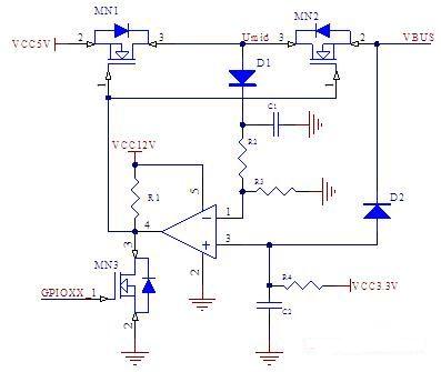
Figure 1 USB VBUS short circuit protection circuit
In the figure, MN1 and MN2 are two MOSFETs on the USB power channel for controlling the output of the 5 volt power supply, and their G terminals are connected to the output of the comparator. The positive terminal potential of the comparator is affected by 3.3 volts and VBUS. The negative potential is determined by Umid through the resistor divider. The value of Umid is always the same as the larger of VCC5V and VBUS. This full play of the role of the forward and reverse cut-off of the diode, and the use of a fast recovery diode in the MOS tube, a comparator can be used to form a window comparator. If the voltage on VBUS falls outside the window (eg 12V supply voltage or ground level), then the comparator outputs a low level, turning off the MOS tube of the supply line. In this way, the 12V voltage can not enter the system, and the system 5V power supply is prevented from overcurrent due to short circuit to the ground, which protects the system from short circuit.
3. Functional argumentation
Assume that the two input terminals of the comparator are U+ and U-, the output potential is UO, and the voltages of diodes D1 and D2 are UD1 and UD2, respectively.
U- = (Umid-UD1)R2/(R2+R3); (1)
In normal operation, U- < U+, UO is high, and the MOS transistor is turned on. In the following, according to the magnitude of the voltage value on VBUS, the two cases are discussed. If the value is large, the comparator output will be inverted and the power output will be turned off.
a. If the VBUS voltage is greater than 5V, because of the reverse cut-off effect of diode D2, there are:
U+ = 3.3V; (2)
And because of the role of fast recovery diodes in MN1 and MN2:
VBUS=Umid; (3)
When U- > U+, the comparator output level is inverted, ie:
(Umid—UD1)R2/(R2+R3)> 3.3 (4)
Namely: Umid > 3.3(R2+R3)/ R2 + UD1 (5)
Let VBUS be VBUSH at this time, combined with (3):
VBUSH= 3.3(R2+R3)/ R2 + UD1 (6)
That is, when VBUS is greater than 3.3 (R2+R3) / R2 + UD1, the comparator will turn off the MOSFET.
b. If the VBUS voltage is less than 3.3V, then there are:
U+ = VBUS+UD2 (7)
Umid = VCC5V (8)
When U- > U+, the output level of the comparator is inverted. From equations (1), (4), (7), and (8), the value of VBUS is set to VBUSL at this time.
VBUSL = (VCC5V - UD1) R2 / (R2+R3) - UD2; (9)
That is, when VBUS is less than (VCC5V - UD1) R2 / (R2 + R3) - UD2, the comparator will turn off the MOS transistor.
Assuming that the compared output voltage is UO, its voltage transfer characteristics are shown in Figure 2:
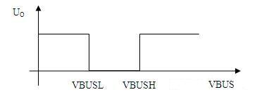
Figure 2 Voltage Transfer Characteristics As can be seen from the above discussion, the circuit shown in Figure 1 can be used to form a window comparator with adjustable threshold value using only one comparator, which realizes effective protection of the USB power supply circuit. When the voltage connected to VBUS is greater than VBUSH or less than VBUSL, the output of the comparator will go low, turning off MOS transistors MN1 and MN2, and isolating system power supply VCC5V from VBUS. The function of C1 and C2 in the circuit is to maintain the voltage at the input of the comparator instantaneously. In addition, the circuit uses three power supplies with different amplitudes. VCC12V is used for the power supply of the comparator. The purpose is to short-circuit the power supply when VBUS occurs. Prevent the negative input voltage of the comparator from being greater than its supply voltage, and also to fully open the MOS transistors MN1 and MN2; VCC3.3V is used as the comparator positive reference voltage. It is not recommended to set the positive reference voltage higher than 3.3V. Because for some USB devices with higher power consumption, the moment of connection will pull VBUS low. During this time, the value of VBUS will be between 3.3V and 5V. If the reference voltage of the positive terminal is greater than 3.3V, the comparator will be in danger of malfunction.
For security reasons, when the system detects that the connected external device is not recognized or belongs to an unsupported device, the system turns off the USB power supply. At this point, the CPU can pull the output of the comparator low by turning on MN3, turning off MN1 and MN2. In this case, the peripheral's power supply circuit will act as a load in series with R4 and D2 to form a loop. Since the input resistance of the peripheral power supply circuit is very low, the comparator's non-inverting terminal will be in a lower potential state, thereby generating a positive feedback effect, causing the comparator to also output a low potential. Since both the comparator and MN3 are open collector/drain structures with line and function, the system CPU can turn off MN3 and continue to maintain the low state of UO through the comparator. Only when the external device is disconnected, the positive input potential of the comparator becomes high, and the power supply line of VBUS will return to normal.
The functions of the above circuits have been verified in practical applications. With this circuit, when the VBUS is short-circuited with the 12V power supply or ground, the 5V power supply in the system is not affected at all, that is, the phenomenon that the voltage is not reversed will not be pulled down and the system will be reset.
CCTV Camera,Consumer Electronics,Video Camera & Accessories,WingHome 3G Camera
Camera Co., Ltd , http://www.nbcamera.com