
1 Introduction
LED display is a public-oriented information display terminal in the subway, which has a very wide range of civilian and commercial value.
At present, subway vehicles operating in China are generally equipped with LED display screens, but the additional functions are less, and the screen display content is single. In order to cooperate with the use of the new subway passenger information system, we have designed a new multi-bus LED display dynamic screen.
The display not only has a variety of bus interfaces when communicating externally, but also uses a single bus and an I2C bus device in the internal control circuit design.
There are two kinds of LED screens on the subway: one is placed outside the compartment, used to display the train running range, running direction and current station name, compatible display in Chinese and English; other service information can also be displayed according to the operation needs; Select static, scroll, pan, waterfall, animation and other effects, the maximum number of characters displayed is 16 × 16 dot matrix characters. The other is the terminal LED display, which is placed in the car. The terminal LED display can preset the terminal station according to the train operation requirements, and display the current terminal station in real time. At the same time, it can also display the current interior temperature, the maximum number of displayed characters. It is 8 characters of 16×16 dot matrix.
2 system composition
The LED display system screen is composed of two parts: the single-chip control unit and the display unit. A single display unit can display 4×16 Chinese characters. If a certain size LED display system is produced, only a few intelligent display units are used. The method of building blocks can be realized, and serial communication is used between display units in the system. In addition to controlling the display unit and transmitting the commands and signals of the upper computer, the control unit also embeds a single bus digital temperature sensor 18B20. Thanks to the modular design of the control circuit, the 18b20 can be upgraded to a modular circuit consisting of Dallas' DS2438 and Honeywell's HIH23610, if required for humidity measurement. In order to meet the communication needs of the whole vehicle, the CAN bus is used for communication between the upper computer and each control unit in the vehicle.
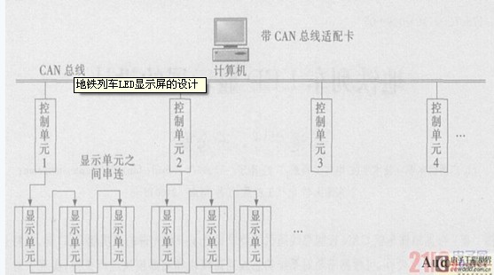
Figure 1 system structure
3 hardware design
The display unit is composed of two parts: an LED display panel and a display circuit. The LED display panel is a 16×64 dot matrix universal intelligent display unit composed of four dot matrix modules, and a single display unit can display four 16×16 dot matrix Chinese characters or a full screen. Symbols, serial communication links between display units in the system, so that the work of the entire system is coordinated. The display circuit consists of two 16-pin cable ports, two 74H245 three-state bus drivers, one 74HC04D six-inverter, two 74H138 eight decoders, and eight 74HC595 shift latches. The core of the control circuit is WINBOND high-speed single-chip microcomputer 77E58, crystal frequency is 24MHz. AT29C020A is 256K ROM, used to store 16×16 dot matrix Chinese character library and 16×8 dot matrix ASCII code table. The AT24C020 is an EP2ROM based on the I2C serial bus, which stores pre-defined statements such as subway station names, greetings, and so on. The interior temperature is measured by a single bus type digital temperature sensor 18b20. The SJA1000 and TJA1040 are CAN bus controllers and transceivers, respectively.
3.1 Control circuit unit design
The whole system is based on Winbond's dynamic single-chip microcomputer 77E58. The 77E58 uses a redesigned microprocessor core. Its instructions are compatible with the 51 series, but since the clock cycle is only 4 cycles, at the same clock frequency, its running speed is generally higher than that. The traditional 8051 is improved by 2~3 times, so the frequency requirement of the single-chip microcomputer during dynamic display of large-capacity Chinese characters is well solved, and the watchdog is also provided. The 77E58 controls the flash memory AT29C020 through the latch 74LS373, which is 256K in size. Since the memory capacity is larger than 64K, the paging method is adopted in the design, that is, the flash memory is paged with P1.1 and P1.2. It is divided into 4 pages, and the addressing size of each page is 64K. In addition to the selection of AT29C020 chip, P1.5 also ensures that P1.1 and P1.2 do not affect AT29C020 when they are multiplexed on the 16-pin cable interface. Misuse. The CAN controller is a key part of communication. In order to improve the anti-interference ability, a 6N137 high-speed optocoupler is added between the CAN controller SJA1000 and the CAN transceiver TJA1040. The MCU performs the chip selection of the CAN controller SJA1000 through P3.0. 18B20 is a single bus device. The device only needs to occupy one I/O port with the single-chip interface. It can directly convert the temperature into a digital signal and serially output it in a 9-digit digital code. In the control circuit, P1.4 is used to complete the pair. 18B20 chip select and data transfer function. The clock line SCL of the AT24C020 and the bidirectional data line SDA are connected to the interface of the P1.6 and P1.7.16 pins of the single chip respectively, which are the interface parts of the control circuit and the display circuit. The hardware connection diagram of the control circuit is shown in Figure 2.
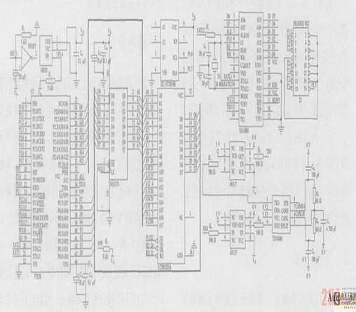
Figure 2 control circuit hardware connection diagram
3.2 display unit connection and control
The display circuit part is connected to the 16-pin line port of the control circuit part through the 16-pin cable (1) port, and the 16-pin cable port (1) transmits the command and data of the MCU to the LED display circuit, 16-pin cable (2 ) Cascade for multiple display screens, its connection is basically the same as the 16-pin cable outlet (1), but note that the R end is connected to the DS end of the 8th 74H595 from left to right in Figure 2. In the cascade, it will be connected in series with the 16-pin cable (1) of the next display (Figure 1). CLK is the clock signal terminal, STR is the row latch terminal, R is the data terminal, G (GND), LOE is the row lighting enable terminal, and A, B, C, and D are row selection terminals. The specific functions of each port are as follows: A, B, C, and D are row selection terminals, which are used to control the specific data sent from the upper computer to the specified row on the display panel, and R is the data terminal, and accepts the data transmitted by the single chip microcomputer. The working sequence of the LED display unit is as follows: after the CLK clock signal end receives a data at the R terminal, the control circuit artificially gives a rising edge of the pulse, and after the STR transmits all the data of one row of data (16×4), the STR gives A rising edge of the pulse is used to latch the data; the LOE is set by the microcontroller to illuminate the line. The schematic diagram of the display circuit is shown in Figure 3.

Figure 3 shows the circuit schematic
4 modular design
Metro vehicles have different requirements for LED displays according to actual conditions. Therefore, we have fully considered this when designing circuits, that is, we can exchange specific modules while ensuring that the main functions and structures are unchanged. This structure makes the LED control circuit have good expandability and ease of use.
4.1 temperature and humidity module
In the hot and rainy areas of the South, although there is constant temperature air conditioning in the car, humidity is also an important indicator for passengers. Our temperature and humidity module has the function of measuring temperature and humidity. The temperature module and the temperature and humidity module have the same socket interface, and all have a single bus structure, all of which are controlled by the P1.4 port, so the interchange is very convenient. The HIH3610 is a three-terminal integrated humidity sensor for voltage output from Honeywell. The DS2438 is a 10-bit A/D converter with a single-bus communication interface. The chip contains a high-resolution digital temperature sensor that can be used for the temperature of the humidity sensor. make up. Figure 4 is a schematic diagram of the temperature and humidity module.
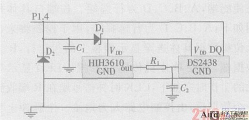
Figure 4 Schematic diagram of temperature and humidity module
4.2485 bus expansion module
As a mature and cheap bus, the 485 bus has an irreplaceable position in the industrial field and transportation field. For this reason, we have designed the 485 bus expansion module, which can replace the original CAN module for external communication. The module uses MAXIM's opto-isolated MXL1535E as the 485 transceiver. In order to ensure control compatibility, the MXL1535E and SJA1000 are both chip-selected through P3.0. In addition, 2500VRMS is electrically isolated between the RS2485 side and the controller or control logic side through the transformer. The TVS diode circuit is added to the output part of the module to reduce line surge interference. Jumpers can also be used to determine whether to load the terminal resistance of the bus. The schematic is shown in Figure 5.
Figure 5485 bus expansion module schematic
5 software design
The system software consists of the upper computer management software and the unit controller control software. The upper computer management software is developed on C++BUILD6.0 on the Windows22000 operating platform, including display mode selection (including static, flashing, scrolling, typing, etc.), scrolling direction selection (including up and down scrolling and left and right scrolling). Dynamic display speed adjustment (ie text flashing frequency, scrolling speed, typing display speed, etc.), display content input and display preview.