
introduction
This article refers to the address: http://
With the rapid development and maturity of positioning and navigation technology, car navigation systems have been more and more widely used in related fields. The function of the car navigation system is to help the user to determine the location of the vehicle and provide the correct steering instructions, so the accuracy of the positioning is an important indicator to measure the performance of a system. At present, commonly used positioning methods include GPS satellite positioning, inertial navigation positioning and combined navigation positioning. The positioning method based on the acceleration sensor ADXL202 described in this paper is one of the inertial navigation positioning. In the car navigation system, the acceleration sensor completes the data acquisition task, obtains the instantaneous acceleration value of the vehicle, and then calculates the offset between the current position and the known reference position by dead reckoning, thereby obtaining the absolute position of the vehicle. . In a short time, the positioning accuracy obtained by this method is very high. For example, in the case of an average acceleration of 28.4 mg, the positioning error obtained in the range of 10 s is about 0.5 m, and the average positioning error of GPS single point is 15 m ― Compared with 20m, it is trivial; but it is conceivable that due to the increase of time, the error accumulation effect will become larger and larger, which seriously affects the accuracy of navigation. Therefore, acceleration sensors are often combined with GPS to form an integrated navigation system to improve positioning accuracy and enhance system performance.
How ADXL202 works
The ADXL202 is a dual-axis accelerometer system from Analogic Devices. The analog input measures dynamic acceleration and static acceleration. The output is a period-adjustable pulse-width modulated signal that can be directly connected to a microcontroller or counter. And it has the characteristics of high performance, high accuracy and low power consumption (input current is less than 0.6mA).
The ADXL202 has a wide range of applications. Mainly used in the fields of inertial navigation, tilt sensing, seismic monitoring and automobile insurance. The ADXL202 has a high degree of integration and a simple structure. It is a monolithic integrated circuit that contains a polysilicon surface micro-processing sensor and signal control circuit to realize an open-loop acceleration measurement structure. Compared to other accelerometers, the ADXL202 greatly increases the operating bandwidth and reduces the effects of noise, with zero gravity deviation and temperature drift. Its structural block diagram is shown in Figure 1:
The ADXL202 sensor consists of an oscillator, X, Y direction sensor, phase detection circuit and duty cycle modulator (shown in Figure 1), and is simple to use, with a digital output interface and an analog voltage signal output interface.
The X and Y direction sensors are two mutually orthogonal acceleration sensors. These two sensors work simultaneously to measure dynamically varying accelerations and constant accelerations. The ADXL measures acceleration in both positive and negative directions and has a wide measuring range for measuring 2g/ 10g acceleration. Figure 2 shows that when the ADXL202 changes with respect to the ground plane direction, the X and Y directions correspond to different outputs, so that a constant acceleration can be calculated.
After the sensor, the cascade phase detector is mainly used to correct the signal and make a judgment on the direction of the signal.
The signal output from the detector drives the duty cycle modulator through a 32K resistor. We can change the bandwidth by connecting capacitors CX and CY to the XFILT and YFILT pins. External capacitors are good for filtering out noise and suppressing zero drift.
After the signal passes through the low pass filter, the duty cycle modulator converts the signal to a digital signal output. The T2 period can be changed by the external resistor of the T2 pin (0.5ms to 10ms), which is suitable for use in applications where the accuracy requirements are different.
The duty cycle signal of the output can be calculated by the counter to calculate the duty cycle. The calculation of the acceleration can be obtained by the formula (1).
A(g)=(T1/T2-0.5)/12.5%..........................(1)
For example, when the acceleration is 0g, the signal width T1 is the same as the idle width (T2-T1), the duty ratio of the output signal is 50%; when the acceleration is 1g, the ratio of the signal width T1 to the idle width (T2-T1) For 5:3, the duty cycle of the output signal is 62.5%.
The ADXL202 can also directly output analog signals, and the analog signals can be processed by A/D conversion to obtain acceleration values.
Design of Combined Car Navigation System Based on ADXL202
The car navigation system introduced in this paper mainly uses acceleration sensor and GPS receiver as the signal source for combined navigation. The embedded microprocessor EP7312 is the core processor of the car navigation system, which provides a working platform for the normal operation of the whole system, and centrally processes the positioning signals from the acceleration sensor ADXL202 and the GPS receiver ITRAX02. The processed result is mapped by the map matching algorithm. On the electronic map, it is displayed on the LCD screen and updated regularly. The entire navigation system structure framework is shown in Figure 2:
The acceleration sensor ADXL202 measures the acceleration value of the vehicle in the X and Y directions of the two-dimensional plane, and outputs it in the form of a pulse width modulation signal. The duty value (ie, T1/T2) is obtained through the CPLD, and the interrupt is triggered, and the ratio is sent to the processor. After 2 integral operations, the relative displacement is obtained and cached in the memory. At the same time, the GPS receiver ITRAX02 receives the wireless-based satellite navigation carrier signal, and after demodulation, sends the signal frame to the embedded microprocessor through the serial interface. The information is extracted according to the specified transmission protocol, thereby obtaining data such as two-dimensional plane position, altitude, ephemeris time, error analysis, and the like, and buffering. After obtaining the relative displacement and GPS positioning data, the microprocessor EP7312 combines the relative displacement data and the GPS data by distributed digital Kalman filtering to obtain the positioning information with higher precision, and uses the map matching algorithm to mark the electronic map. The current position is drawn, and the positioning and navigation information are provided to the user in time by refreshing the LCD screen. The system uses the acceleration sensor and GPS as the data source for combined navigation, which can not only take advantage of the short-term positioning accuracy of the acceleration sensor, but also the autonomous navigation without external interference. It can also play the long-term stable positioning of GPS navigation, and has the advantage of simple use and reduced error. The impact of accumulation has improved system performance.
CPLD design
In the application of in-vehicle navigation systems, it is inevitable that there will be thunderstorms and other paths such as mountains and mountains. Such conditions will naturally cause serious interference to GPS signals. In order to reduce the inaccuracy of positioning, the acceleration sensor is used for further positioning while using the GPS receiver for positioning. CPLD mainly realizes the calculation of the duty ratio of two signals.
The processing of CPLD is shown in Figure 3:
The counting controller is used to control the frequency divider so that the frequency of the output signal of the frequency divider is 1000 times the output frequency of the sensor. The signal output by the frequency divider samples the sensor output signal, counts the number of samples with a value of one cycle, and stores it in the buffer.
After the counter is full, an interrupt is triggered to inform the CPU to read the data.
For low power considerations, the entire CPLD is controlled by the enable signal EN. The EN signal can be controlled by the GPIO port of the EP7312.
Application software design
We develop navigation programs on the Windows CE operating system platform. Windows CE is a small, ROM-based operating system with Win32 subset API from Microsoft Windows. Compared with other embedded operating systems, it has strong memory management, file management and GUI functions. In the car navigation system, there are high requirements for displaying map scheduling and user interaction interfaces. Therefore, developing applications based on Windows CE is very suitable.
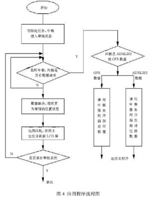
The car navigation system application is a multi-tasking program. After startup, it initializes the serial port of the processor connected to the GPS receiver ITRAX02, the serial port 2 connected to the ADXL202, and the LCD control connected to the color LCD screen for displaying the driving position of the vehicle. Device. As a central processing unit, the EP7312 monitors the serial port 1 and serial port 2 interrupt signals in real time. When the pulse modulation signal of the ADXL202 is converted to the duty cycle value by the CPLD, it will be sent to the processor, which will cause the corresponding serial port interrupt.
When EP7312 detects the interrupt signal, the interrupt controller judges to find the entry address of the corresponding interrupt service program, and calls the program to process it; when the GPS receives a frame of satellite signal, it also triggers the corresponding serial port interrupt, and the interrupt controller judges to find the corresponding The entry address of the interrupt service routine is called by the calling program. The interrupt service program that processes the duty value first buffers the received data. After filtering, the relative displacement in one cycle is obtained after two integrations, and the record is exited and the CPU usage right is surrendered. The interrupt service program that processes the GPS data is first buffered and received. The data is extracted from the direction and location information according to the pre-agreed format, recorded, exited and surrendered to the CPU. The data processing task is mainly to combine the relative displacement data and the GPS position data through the distributed digital Kalman filtering method to compensate for the defect that the GPS data positioning accuracy is not high enough and the acceleration sensor error accumulation, so as to obtain the positioning information with higher precision. Exit and hand over the CPU usage rights. After the map matching task is called, the map matching algorithm is used to project the positioning information onto the electronic map for plotting, and the positioning information is provided to the user in time by refreshing the LCD screen. The application flow is shown in Figure 4.
Conclusion
At present, the system has been designed and entered the final test phase. After a period of testing, hardware performance and software performance are good, which is a feasible design idea.
Thanks to the diversified sizes and dimensions of Lfp Battery cells, we are enabled to build up a complete set of battery packs with working voltage range from 12V up to 600V. Please do not hesitate to contact us if you are in need of electric power for automotive or energy storage solution. We will provide you with a great variety of customized services.
Customized Lifepo4 Lithium Battery
Customized Lifepo4 Lithium Battery,Lifepo4 Lithium Battery,Customized Rechargeable Battery,Customized Lithium Battery
FORZATEC CO., LIMITED , http://www.forzatec.com