
We know that electromagnetic interference that causes equipment performance degradation or failure must have three elements at the same time. First, there is an electromagnetic field, followed by an interference source and an interfered source, and finally a coupling path with electromagnetic interference to remove energy. The source of interference is passed to the victim. Therefore, in order to solve the electromagnetic compatibility of equipment, it is necessary to analyze around these three points. In general, for the control of EMI, we mainly use three measures: shielding, filtering, and grounding. Although these three methods have independent functions, they are related to each other. Good grounding can reduce the shielding and filtering requirements of the device, and good shielding can also make the filter requirements lower. Below, we will introduce shielding, filtering and grounding separately.
1 shield
Shielding can effectively suppress electromagnetic interference propagating through space. There are two purposes for shielding. One is to limit the internal radiated electromagnetic energy from leaking out of the control area, and the other is to prevent external radiated electromagnetic energy from entering the internal control zone. According to the shielding mechanism, we can divide the shielding into electric field shielding, magnetic field shielding, and electromagnetic field shielding.
1.1 Electric field shielding
In general, electric field induction can be seen as a coupling between distributed capacitors. Figure 1 is a schematic diagram of electric field induction.
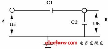
Figure 1 Schematic diagram of electric field induction
Where A is the source of interference and B is the device under induction, where the relationship between Ua and Ub is
Ub=C1*Ua/(C1+C2)
C1 is the distributed capacitance between A and B; C2 is the capacitance to the ground of the sensing device.
According to the schematic diagram and the equation, in order to weaken the geomagnetic induction above B, the method used is
Increase the distance between A and B and decrease C1.
Reduce the distance between B and ground and increase C2.
Place a thin metal sheet between AB or place A with a metal shield to cover A, and C1 will tend to a value of zero.
Relatively speaking, 1 and 2 are relatively easy to understand. Here, the third method is mainly analyzed. It can be seen from Figure 2 that after the shield is inserted (the shield is grounded). This results in two distributed capacitors C3 and C4, where C3 is shorted to ground by the shield, which does not affect the electric field induction at point B. The ground capacitance of the sensing object B and the distributed capacitance to the shielding plate, C3 and C4, are actually in parallel positions. Thus, the induced voltage ub' of the B device should be the voltage at which the voltage at point A is divided by the residual capacitance C1' between A and B and the parallel capacitors C2 and C4, that is,
Ub=C1'*Ua/(C1'+C2+C4)
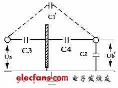
Figure 2 Electric field sensing diagram after adding metal plate
Since C1' is much smaller than the shielded C1, the induced voltage at B is much reduced. Therefore, this grounded metal cover is often used as a shield.
The following is a summary of the main points of the electric field shielding:
It is better to place the shielded metal plate close to the protected device, which will result in a larger C4 and reduce the induced voltage of the electric field.
The shape of the shielding plate has a significant influence on the shielding performance. For example, a fully encapsulated metal box can have the best electric field shielding effect, and an open hole or a gapped shielding cover can have the best electric field shielding effect, and Holes or shields with gaps, the shielding effectiveness will be affected to varying degrees.
The material of the shielding plate is preferably a benign conductor. There are no special requirements for thickness.
1.2 Magnetic field shielding
Since the magnetic field shielding is usually shielded from direct current or very low frequency fields, the effect is much worse than the electric field shielding and the electromagnetic field shielding. The main means of magnetic field shielding is to rely on the low magnetic reluctance of the high magnetic permeability material to score the magnetic flux. The role of the road makes the magnetic field inside the shield greatly weakened.
Points to note for magnetic field shielding:
Reduce the magnetoresistance of the shield (by selecting a high permeability material and increasing the thickness of the shield)
Keep a certain distance between the shielded device and the shield to reduce the magnetic flux passing through the shielded device.
For the inevitable use of gaps or air inlets, try to make the gaps or air outlets strip, and reduce the magnetic flux along the direction of the electromagnetic line.
For the shielding of a strong electric field, a structure of a double-layer magnetic shield can be employed. In order to shield the external strong magnetic field, the outer layer of the shield should be made of materials that are not easily magnetically saturated, such as silicon steel, and the interior can be made of a highly magnetically permeable material that easily reaches saturation. Because the weakened portion is shielded for the first time, most of the second weakening, if high magnetic permeability is used, it will cause reflection between one layer and two layers into a shield. If you want to shield the internal magnetic field, the opposite is true. The shield is typically grounded through a non-magnetic material.
1.3 electromagnetic field shielding
Electromagnetic field shielding is a measure of the use of a shield to block the propagation of electromagnetic fields in space. Unlike the shielding mechanism of the electric and magnetic fields in front, the electromagnetic shielding has three processes for the attenuation of electromagnetic waves:
When the electromagnetic wave reaches the surface of the shield, the impedance is discontinuous due to the discontinuity of the impedance at the interface between the air and the metal. This reflection does not require the shielding material to have a certain thickness, and only the discontinuity at the interface is required.
The electromagnetic wave entering the shield is attenuated in the shield.
After passing through the shielding layer, the other shielding body of the shielding layer is reached, and since the impedance is discontinuous, reflection is generated and returned to the shielding body.
From the above three processes, the electromagnetic shield's attenuation of electromagnetic waves is mainly reflection and absorption attenuation.
Chaff Cutter,Chaff Cutter Machine,Mini Chaff Cutter,Hand Chaff Cutter
Hunan Furui Mechanical and Electrical Equipment Manufacturing Co., Ltd. , https://www.thresher.nl