
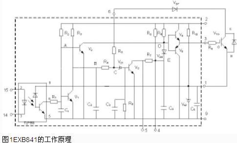
 Figure 1 shows the driving principle of EXB841. It mainly has three working processes: normal open process, normal shutdown process and overcurrent protection operation process. The PWM control signal is applied between the feet 14 and 15 and when the trigger pulse signal is applied to pins 14 and 15, about 16V IGBT turn-on voltage is generated across the GE; when the trigger control pulse is cancelled, it generates -5.1 across the GE. V IGBT turn-off voltage. The over-current protection operation process is based on the magnitude of the Uce between the IGBT's CE voltage to determine whether it is overcurrent, and Uce is detected by the diode Vd7. When the IGBT is turned on, in the event of a large current failure such as a load short-circuit, Uce will rise a lot, making Vd7 cut off, and the 6-pin of EXB841 “hangsâ€, the potentials of points B and C start to rise from about 6V, and when it rises to 13V Vz1 is broken down, V3 is turned on, C4 is discharged through R7 and V3, the voltage at point E is gradually decreased, and V6 is turned on, thereby reducing the GE voltage Uce of the IGBT, achieving soft turn-off, and completing the EXB841 protection of the IGBT. The emitter potential is -5.1V, determined by the zener diode Vz2 inside the EXB841
 LED Dimmable Lamp,LED Dimmable Lights,Dimmable LED Bulb
LED Linear Light LED Spotlights Co., Ltd. , http://www.chledlamps.com