
Thermal characteristics and longevity are two important properties of LEDs, which are highly valued by people and have a correlation between them. However, the detection of these two performance parameters is challenging. Based on the requirements of relevant domestic and international standards and the latest research, this paper comprehensively analyzes the testing requirements and methods of LED thermal characteristics parameters and life indicators, and introduces advanced testing equipment and features at home and abroad.
1 Overview
In recent years, LED lighting technology has developed rapidly. At the same time, LED's light color, color temperature, color rendering and other light color indicators have attracted much attention. At the same time, the thermal characteristics and life of LED have been paid more and more attention, especially thermal characteristics. It has a significant impact on the performance and lifetime of LED Light color. However, the detection of thermal properties and lifetime is challenging.
The thermal characteristics of LEDs mainly include LED junction temperature, thermal resistance, transient curve (heating curve, cooling curve) and so on. The junction temperature refers to the PN junction temperature of the LED. The thermal resistance refers to the ratio of the temperature difference between the LED heat dissipation channel and the dissipation power on the channel. It is used to characterize the heat dissipation capability of the LED. Research shows that the lower the thermal resistance of the LED The better the heat dissipation performance, the higher the corresponding LED light efficiency and the longer the life. The key to the detection of thermal characteristics is the accurate measurement of the junction temperature of the LED. The existing test for the junction temperature of the LED generally has two methods: one is to measure the temperature of the surface of the LED chip by infrared temperature measurement and regard it as an LED. Junction temperature, but the accuracy is not enough; the other is to obtain the PN junction temperature by temperature-sensitive parameter (TSP), which is the most common LED junction temperature test method. The technical difficulty lies in the test equipment. The requirements are higher.
The life of an LED is mainly manifested by its light decay. The LED light output is usually attenuated to 70% or 50% of the initial light output as an indicator of life failure, that is, the luminous flux maintains its lifetime. However, since LEDs are highly reliable devices, the lifetime generally exceeds several thousand hours or even more than 10,000 hours. It is very difficult to directly measure the waiting for light decay to a specified value in industrial applications.
2, LED thermal characteristics test
2.1 LED junction temperature and thermal resistance measurement
US EIA/JESD51 "Methodology for the Thermal Measurement of Component Packages" series of standards and national standards SJ20788-2000 "Semiconductor diode thermal impedance test method", GB/T4023-1997 "Semiconductor device discrete devices and integrated current Part 2: rectifier diode 》, QB/T 4057-2010 "Performance Requirements for LEDs for General Lighting" and other international and domestic standards have introduced the method of measuring junction temperature and thermal resistance through temperature sensitive parameter TSP. For LEDs, TSP is the forward voltage across the PN junction. Under the determined current, the forward bias of the LED is approximately inversely proportional to the junction temperature, and the change in junction temperature is obtained as follows: 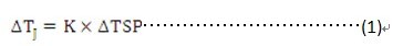
In equation (1), K is the temperature sensitivity coefficient, which can be obtained from: 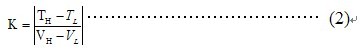
In equation (2), VL is the forward voltage of the LED under the measurement current IM (small current) when the low junction temperature TL (such as 25 ° C), and the LED is measuring the current IM when the VH is the high junction temperature TH (such as 100 ° C) The forward voltage underneath.
The timing of the LED junction temperature measurement is shown in Figure 1: 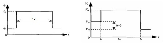
Figure 1 (a) current timing diagram Figure 1 (b) voltage timing diagram
1) First, apply a test current IM to the LED, and measure the forward junction voltage VFI;
2) Replace the IM with the heating current IH to the two ends of the LED to be tested, and heat it for a certain period of time (tH) until the LED reaches a steady state, and measure the heat dissipation power (PH) on the heat dissipation channel of the measured LED;
3) Re-use IM to quickly replace IH to both ends of the LED to be tested, and measure the forward junction voltage drop (VFF);
4) Calculate the junction temperature and thermal resistance of the LED:
According to the above principle, the junction temperature calculation formula is: 
The thermal resistance calculation formula is: 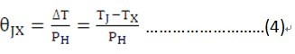
In the formula (3), the initial temperature, in the formula (4), is the temperature of a specified point on the heat dissipation channel, for example, the ambient temperature or the case temperature. For LEDs, part of the input electrical power is used for LED illumination, and the other part generates heat, and the heat dissipation power PH is often difficult to distinguish from the total input electric power, so for convenience and simplified measurement, QB/T 4057-2010 proposes " Refer to the concept of thermal resistance, which uses the total input power instead of the heat dissipation power in equation (4). The “reference thermal resistance†has been used more and more because of its convenient measurement and good reproducibility.
Under the action of heating current IH, it is also meaningful to monitor the junction temperature rise of the LED and obtain the heating curve. Figure 2 shows a typical heating curve, which can not only determine whether the LED reaches thermal equilibrium, but also the structure and heat dissipation capability of the LED. Analysis has a reference role.
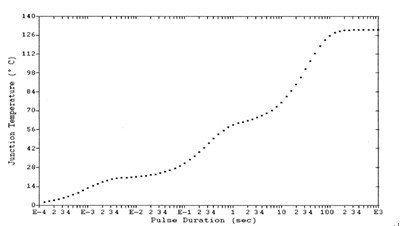
Figure 2 heating curve
The technical difficulty in obtaining the heating curve is that the test current and heating current switching time must be short enough, and the transient data must be collected very quickly. The switching time and data acquisition time generally reach several to ten microseconds. Otherwise, the actual change process of the LED junction temperature cannot be reflected, resulting in the thermal resistance of the final test being greatly underestimated.
Dual Function Key Switches is a Key Switchesthat combines Electric Key Switch and Mechanical Key Lock, which is Simultaneously have power control and could mechanically protect the equipment from invading.
Our company's Key Lock Electrical Switches has mounting dimensions of 12mm and 19mm. This 2 Position Key Switch is widely used in the field of security products, which not only can achieve the function of switching power supply but also could protect customer`s confidential data.

Below are the specifications:
Electrical and row piece dual function
Zinc alloy die cast housing and cylinder
Barrel chrome or nickel plated standard
Lock case, white iron cover
4 disc tumbler mechanism
Brass tubular keys or Bilateral bilateral milling copper key, nickel plated
The iron bar has a standard size of 13mm or Row Piece, can be made according to customer requirements.
Key may be withdraws in one or both position aSilver terminals and Contacts.
Dual Function Key Switches
Dual-Function Switches,Dual Push Button Switch,Automatic Transfer Switch,Changeover Switch
YESWITCH ELECTRONICS CO., LTD. , https://www.yeswitches.com