
TPMS scheme based on radio frequency transceiver chip CC1100
0 Preface
The development of the automotive industry has driven the development and technological upgrading of the automotive equipment industry. Among them, following the airbags and ABS (anti-lock brake system), the TPMS (automobile tire pressure detection system) that appeared in the international automotive field is known as a new generation of high-tech automotive safety equipment. In the process of high-speed driving of a car, tire failure is the most worrying and difficult to prevent for all drivers, and it is also an important cause of sudden traffic accidents. According to statistics, 70% to 80% of traffic accidents on highways are caused by flat tires. How to prevent a flat tire has become an important issue for safe driving. According to analysis by relevant experts, maintaining standard tire pressure and timely detection of tire leaks are the keys to preventing tire punctures.
Foreign countries began to study tire pressure monitoring devices since the late 1970s. In summary, they are mainly divided into two types: one is based on wheel speed (indirect); the other is based on pressure sensor (direct). Now the United States and some European countries have adopted TPMS as a must-have equipment for automobiles. Although the research on TPMS in China started late, in the national standard promulgated on November 24, 2003-"Technical Conditions for the Operation Safety of Motor Vehicles (Consultation Draft)", the installation of tire pressure detection devices is explained. Has begun to attach importance to the development of TPMS.
The TPMS proposed in this paper adopts a modular design and standardized programming. Its core part is to send and receive the collected temperature and pressure data wirelessly. The wireless transceiver chip CC1100 produced by Chipcon Company can solve this problem well. It supports ZigBee wireless network technology, low power consumption, no need to apply for frequency points, and reliable transmission.
1. Tire working characteristics and TPMS technical requirements
The tire is made of rubber and frame material, and is installed on the outside of the tire. It supports the weight of the car, absorbs and mitigates impact and vibration, and maintains good adhesion between the car and the ground, thereby effectively transmitting the driving torque or braking torque of the car. . The working characteristics of tires have a great influence on the safe driving of cars.
The main factors that affect the normal operating characteristics of tires are:
a) The tire temperature is too high. The high ambient temperature and the friction between the tire and the ground during high-speed rotation may cause the tire temperature to be too high, thereby aging the rubber and shortening the service life of the tire.
b) The air pressure inside the tire is too high or too low. When the load of the car is too high or the temperature is too high to cause the inflation of the gas in the tire, it will cause the internal pressure of the tire to be too high and a tire puncture phenomenon will occur.
c) Leakage caused by tire air leakage will also increase the friction between the tire and the ground, which not only consumes fuel, but also shortens the service life of the tire.
The mechanical performance of the tire is mainly reflected by the temperature and pressure inside the tire. Therefore, as long as the TPMS can detect the temperature and pressure inside the tire in real time, it can analyze the operation status of the tire.
Since the TPMS transmission system is in the closed state of the tire, the main technical requirements of the system are as follows:
a) Taking into account the installation and use of button battery power supply, the sampling transmitter should be small in size and low in power consumption.
b) The system can recognize the temperature and pressure measurement values ​​sent by each sampling transmitter.
c) The system can filter out any data sent by other cars.
d) The receiving end can display the temperature and pressure measurement values ​​sent from each sampling transmitter in real time, and can carry out alarms for exceeding the limit.
2. TPMS principle and hardware design
2.1 TPMS system structure
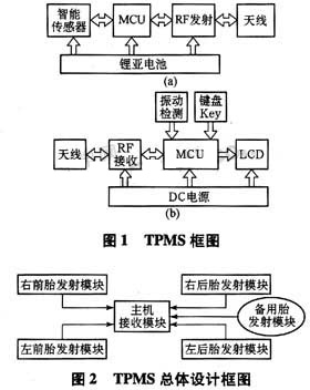
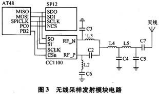
TPMS consists of a sampling transmitter module and a receiver module. The sampling transmitter module is installed in the tire, and the receiving module is installed in the car. The sampling and transmitting module samples the air pressure and temperature signals detected by the pressure sensor, performs data analysis processing by the MCU (micro control unit) and sends them to the radio frequency transmitting circuit, and the signals are modulated and transmitted to the receiving module. The demodulation circuit of the receiving module amplifies and demodulates the radio frequency signal emitted by the transmitting module, and then sends the digital signal to the MCU. The MCU makes corresponding processing, such as updating the current pressure value, sound and light alarm, etc., so as to realize the display and monitoring of the tire pressure. The block diagram of the TPMS structure composed of main chips such as sensors, MCUs, transmitters and receivers is shown in Figure 1. The overall layout of the system is shown in Figure 2.
2.2 System function and overall design
The TPMS sampling transmitter module works under the conditions of severe vibration, large changes in ambient temperature difference, and inconvenience of overhaul at any time. Therefore, all devices are required to have high reliability and stability, and can adapt to a wide temperature range and severe vibration. In order to reduce the size of the TPMS sampling transmitter module, save power consumption and enhance functions, a chip with low power consumption and strong functions needs to be selected.
In order to extend the service life of the battery of the TPMS sampling transmitter module and enable it to work for 3 to 5 years, power saving of the system is a very important issue. Only when the system goes to sleep most of the time can it save power and extend battery life.
The main functions of the system are as follows:
a) Monitor the temperature and pressure of each tire in real time.
b) Alarm when the pressure of a tire is too high or too low.
c) When the tire maintenance is replaced, the position number of each tire sampling transmitter module can be reset.
d) It can display the current pressure value and temperature value of each tire.
When installing the sampling transmitter module, turn on the five modules one by one to register. The receiving end receives the unregistered ID (identification code) code sent by the sampling and transmission module and performs registration, and the corresponding tire number is manually set. The MCU at the receiving end stores the ID and tire code in the E2PROM for normal operation.
If the module in the tire fails, you can delete the sample transmitter module ID to be changed from the host receiver module and re-register. After the tire maintenance is transposed, the tire code can be reset in the host receiving module.
Due to the non-repeatability of the IDs of the sampling and transmitting modules, the mutual interference between the five tire sampling and transmitting modules of the same vehicle or the sampling and transmitting modules of different vehicles can be effectively avoided.
When the car is driving, the vibration sensor in the receiving module detects the car vibration signal, and the TPMS is activated. The host sends a command through the transceiver chip to wake up the sample transmitter module from sleep. The sampling and transmitting module packages and sends out the temperature and pressure values ​​inside the tire. The receiving module compares the ID in the received data packet with the ID and tire code stored in the host E2PROM to determine which tire's data is to be stored and displayed. When the tire pressure is too high or too low, an alarm is given. When the car stops, the vibration sensor cannot detect the vibration signal, and the TPMS enters the sleep state. When the car is stopped, if you want to know the temperature and pressure value inside the tire, the driver can activate TPMS by pressing the button to read the current pressure and temperature value of the tire.
2.3 Design of wireless sampling transmitter module
SP12, ATmega48 (hereinafter referred to as AT48) and CC1100 constitute the sampling and transmitting module. SP12 is a pressure sensor. The measuring range is 100 kPa ~ 4 500 kPa, with A / D and SPI (Serial Peripheral Interface) inside, which can be easily applied in TPMS. SP12 is a 14-pin SMD package and does not require other external components.
AT48 is an extremely low power 8-bit CMOS MCU based on AVR enhanced RISC (Reduced Instruction Set Computer) structure produced by ATMEL. The normal mode is: 1 MHz, 1.8 V / 300 μA; 32 kHz, 1.8 V / 20 μA (including the oscillator); the power-down mode is: 1.8 V / 0.5 μA.
CC1100 is a low-cost single-chip programmable UHF transceiver chip based on Chipcon 'Smart RF (radio frequency) technology, designed for low-power wireless applications. Its working frequency band is flexible and can be set in the ISM (industrial, scientific and medical) and SRD bands at 315 MHz, 433 MHz, 868 MHz and 915 MHz. Low power consumption (receive current is less than 16 mA, transmit current is less than 30 mA, sleep current is less than 10 μA, and supports ZigBee wireless network technology. The main operating parameters of CC1100 can be changed through SPI interface programming, which makes CC1100 more flexible to use.
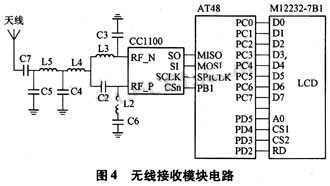
The circuit design of the sampling transmitter module is shown in Figure 3. The sensor SP12 sends the collected data to the AT48, and the AT48 sends the data to the CC1100 through the SPI port, and then converts the CC1100 into a data frame and sends it to the host receiving module.
The transmission frequency of the module is determined by the crystal oscillator of the transmitter chip CC1100 and external components. The system selects a transmission frequency of 433 MHz, and then pins 8 and 10 are connected to a 26 MHz crystal. C2 is (3.9 ± 0.25) pF, C3 is (3.9 ± 0.25) pF, C4 is (8.2 ± 0.5) pF, C5 is (5.6 ± 0.5) pF, C6 is 220pF ± 5%, C7 is 220pF ± 5%, L2 is 27nH ± 5%, L3 is 27nH ± 5%, L4 is 22nH ± 5%, and L5 is 27nH ± 5%. Resistor R2 is used to set an accurate bias current. C3, C2, L2, and L3 form a balanced converter to convert the differential RF port on the CC1100 to a single-ended RF signal. CC1100 supports amplitude, frequency and phase-shift modulation formats, which can be configured through register MDM-CF2.MOD_FORMAT.
Configure CC1100 register WORCTRL to configure it as WOR (electromagnetic wave activation) mode, and set register bit MCS1.RX-OFF_MODE. When the sample transmission module receives a valid data packet, CC1100 is activated and enters the transmission mode and wakes up the AT48.
2.4 Design of wireless receiving module
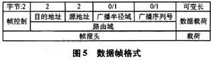
The receiving circuit consists of wireless transceiver chips CC1100 and AT48, as shown in Figure 4.
CC1100 and AT48 transmit data through SPI port. In the receiving state, with SCLK as the synchronous clock, CC1100 receives valid data information and sends the digital signal to the SPI port of AT48. AT48 will decode the received data, extract the temperature and pressure values ​​of each tire from the data stream, and then make corresponding processing, such as updating the current temperature and pressure values, and sound and light alarms. Before receiving, AT48 writes relevant data to SPI data register SPDR, initializes CC1100 and configures the corresponding register, and then waits to receive data.
3. Software design
3.1 System topology
The receiving module and the sampling module adopt the master-slave method. The receiving module can be regarded as the master device, and the sampling module inside the tire is the slave device. In order to achieve reliable wireless communication between the sample transmitting module and the receiving module, a certain protocol must be performed between the two. The ZigBee network includes a coordinator, FFD (full-function device) and RFD (simplified function device), and supports three network topologies: star network, tree network and mesh network. Considering that ordinary cars have 4 tires and 1 spare tire, the sampling transmitter module in each tire serves as a child node of the ZigBee network. No data transmission is performed between the child nodes, and only the receiver module in the car communicates , So choose star topology. The RFD child node transmits the data to the receiving end in the form of a frame through the ZigBee wireless network, and then the host of the receiving end analyzes and processes the data and displays it. Figure 5 is the data frame format of the ZigBee network.
3.2 Software design
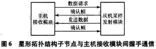
The communication mode between the sampling transmitter module and the receiving module (host) is shown in Figure 6.
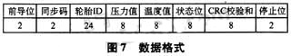
The data frame format sent by the sampling transmitting module to the receiving module is shown in FIG. 7.
3.2.1 Sampling and transmitting module program flow
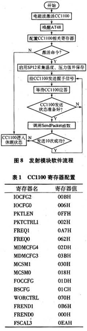
The main program flow of the sampling transmitter module is shown in Figure 8. The CC1100 is activated when it detects a wake-up command and wakes up the MCU. The MCU configures CC1100 to enter transmit mode. After the MCU acquisition sensor detects the data in the tire and processes it, it is sent to the host by CC1100. After the transmission is successful, the CC1100 and the MCU re-enter the sleep state. The register configuration is shown in Table 1.
3.2.2 Receiving module program flow
The program flow of the receiving module is shown in Figure 9.
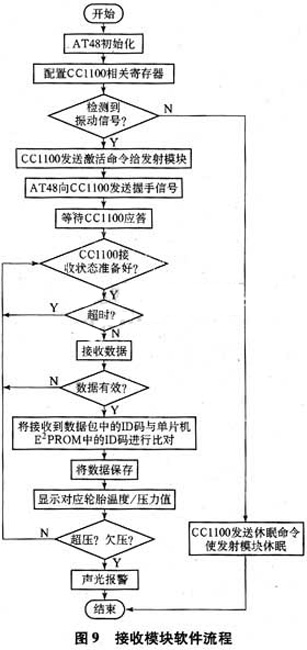
After turning on the power, AT48 initializes first, and then configures CC1100. When the MCU detects the vibration signal, it sends an activation command to the sampling transmitter module. After the command is successfully sent, it immediately enters the receive mode. If the CC1100 is ready to receive, it can receive data. If the received data is valid, the received ID is compared with the ID code stored in the E2PROM of the single-chip microcomputer. If it matches one of the IDs, the data is processed and saved. When it detects that the temperature and pressure value deviate from the normal value, it will alarm to remind the driver to pay attention. The driver can also view the currently detected temperature and pressure values ​​inside the tire through the display.
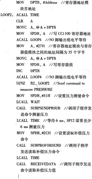
The specific program segment is as follows:
4 Conclusion
The TPMS based on ZigBee wireless network technology and wireless transceiver chip CC1100 proposed in this paper makes full use of the characteristics of wireless transceiver chip CC1100, AT48 and sensor SP12, adopts low power consumption and low complexity ZigBee network technology as the communication protocol, in the electromagnetic wave activation mode Next, after sending the data packet successfully, CC1100 can enter deep sleep state, which greatly reduces the power consumption of the module. Each tire is set with a fixed ID code to avoid outside interference. The driver can manually read the temperature and pressure of any tire in the cab to monitor the tire status in real time and prevent tire failure. The realization of this system provides an effective way to prevent the car from puncturing.
For Sony:
For Xperia Z4V, For Xperia Z3V
For Google:
For Nexus 4, For Nexus 5, For Nexus 6, For Nexus 7
For MOTORALA:
For Moto Droid Turbo, For Moto Droid Turbo 2, For Moto Droid 5
For NOKIA:
For Lumia 920, For Lumia 928, For Nokia Lumia 93, For Lumia 950, For Lumia 950 XL, For Lumia 1020, For Nokia Lumia 1050, For Nokia Lumia 822, For Nokia Lumia 735
For HTC:
For HTC ONE MAX T6, For HTC Incredible 4G, For HTC ONE mini 2, For HTC Droid DNA
For LG:
For LG Nexus 4, For LG Nexus 5, For LG G Pro, For LG D1L, For LG LTE2
For Iphone:
For Iphone8/X/XR/XS Max
Compabile Models:
For Samsung:
For Galaxy S6, For Galaxy S6 Edge, For Galaxy S6 Edge+,
For Galaxy S6 Active, For Galaxy S6 Duos, For Galaxy Note Edge,
For Galaxy S7, For Galaxy S7 Edge, For Galaxy Note 5
For Galaxy S8, For Galaxy S8 Plus, For Galaxy Note 8
For Galaxy S9,For Galaxy S9 Plus
For Others:
Guangzhou HangDeng Tech Co. Ltd , https://www.hangdengtech.com