
Resistance is a real physical component that exists in electrical circuits. We can understand the relationship between voltage, current, and resistance through Ohm's Law, which states that U = I × R.
To explore this relationship more deeply, let’s look at a simple circuit diagram. This basic setup includes just one power source, one resistor, and some connecting wires.
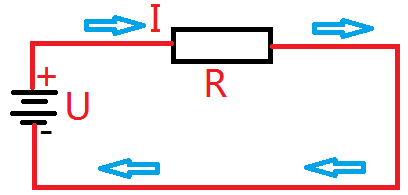
Of course, the resistance of a resistor can be directly measured using a multimeter. However, characteristic impedance is a different concept altogether. If you measure a 50-ohm characteristic impedance with a multimeter, it may appear as a short circuit. This highlights the importance of distinguishing between resistance (which is a direct measurement) and characteristic impedance, which is a property of transmission lines.
It’s similar to how degrees Celsius and degrees of an angle are both called "degrees," but they represent completely different things. Resistance is a well-understood physical quantity, so we won’t go into detail here. Instead, let’s dive into the concept of characteristic impedance and when it becomes important.
Characteristic impedance is closely related to radio frequency (RF) signals. To understand it, we first need to grasp what RF is. Devices like radios, mobile phones, and Wi-Fi systems transmit energy through antennas. Once that energy is sent out, it doesn’t return — much like firing a bullet from a gun; it goes forward and doesn’t come back.
When RF signals travel along a conductor, we want them to move smoothly without being reflected back. If energy is reflected, it means the signal isn’t transmitted efficiently.
Let me use an analogy to explain characteristic impedance more clearly:
Imagine two copper traces on a PCB, both very long and with the same thickness. The only difference is their width: one is 1 unit wide, and the other is 2 units wide. Even though they’re on the same board, the wider trace has a different behavior due to its geometry.
The figure below shows these two wires in detail.

If we connect the same RF source to both, after the same short time T, we’ll notice differences. The RF voltage is the same for both, and the signal travels the same distance (approximately at the speed of light). The only difference is the width of the wire.
Because the second wire is twice as wide, it has more capacitance — meaning it takes more charge to fill the space. So Q2 is twice Q1. Since current equals charge over time (i = Q/T), the current in the second wire is also twice that of the first.
Now, recall that resistance is voltage divided by current. Similarly, characteristic impedance is RF voltage divided by RF current. Since the voltage is the same, and the current doubles, the characteristic impedance of the second wire is half that of the first.
This explains why wider traces have lower characteristic impedance. It also shows that characteristic impedance depends on the geometry of the line, not its length.
Other factors, such as material properties and spacing from the ground plane, also influence characteristic impedance. In simple terms, characteristic impedance is a way to describe how much a transmission line resists the flow of RF energy.
Understanding Reflection in Transmission Lines
In our previous example, we assumed the wire was infinitely long. But in reality, all wires have a finite length. When an RF signal reaches the end, it can't continue forward, so it reflects back — just like shouting at a wall and hearing an echo.
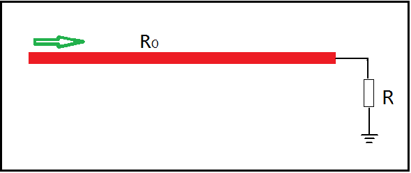
If we connect a resistor at the end of the line, it can absorb the RF energy. Why not just use the wire itself? Because the wire transmits energy, but it doesn’t consume it — it behaves more like a capacitor or inductor. A resistor, on the other hand, is designed to dissipate energy.
There are three key cases to consider:
1. When the load resistor R matches the characteristic impedance RO, all the energy is absorbed, and no reflection occurs — like a perfectly matched system.
2. When R is infinite (open circuit), all the energy is reflected back, doubling the voltage at the end.
3. When R is zero (short circuit), the reflected voltage is -1 times the source voltage.
What is Impedance Matching?
Impedance matching ensures maximum power transfer from a source to a load. It’s crucial in RF systems, where mismatched impedances can cause signal loss or damage. However, it’s not used in power circuits, as it could lead to overheating or failure.
You often hear about 50-ohm or 75-ohm characteristic impedances. Why 50 ohms specifically? It’s a standard chosen for general RF applications. Wires and cables are made with 50 ohms because most loads are designed to match that value. Deviating from this value leads to poor signal transmission.
Redundant Power Supply Series,Full Modular Redundant Power,800W Redundant Power Supplies,Redundant Server Power Supply 2000W
Boluo Xurong Electronics Co., Ltd. , https://www.greenleaf-pc.com