
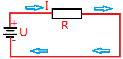
Resistance is a real physical component that exists in electrical circuits. We can understand the relationship between voltage, current, and resistance through Ohm’s Law, which is expressed as U = I × R. This fundamental law allows us to predict how these three quantities interact in any given circuit.
To explore this further, let's look at a simple circuit diagram. The basic setup includes a power supply, a resistor, and connecting wires. This configuration helps illustrate how voltage, current, and resistance are interrelated in a practical scenario.
In addition to measuring resistance directly with a multimeter, there's another important concept called characteristic impedance. Unlike regular resistance, characteristic impedance is not something you can measure directly with a multimeter—it behaves differently. For example, if you try to measure a 50-ohm characteristic impedance with a multimeter, it might appear as a short circuit. This highlights the fact that resistance and characteristic impedance are two distinct concepts, much like how degrees Celsius and degrees of angle are different units for different purposes.
While resistance is a well-understood concept, characteristic impedance plays a crucial role in high-frequency applications such as radio frequency (RF) systems. RF signals, like those used in cell phones, Wi-Fi, and radio communications, transmit energy from an antenna outward. Ideally, this energy should not reflect back, just as a bullet fired from a gun doesn't return to the barrel.
When RF signals travel along a conductor, we want them to be transmitted efficiently without reflection. If energy is reflected, it indicates poor signal transmission. To better understand this, let's consider an analogy.
Imagine two long copper traces on the same PCB board. Both have the same thickness, but one is twice as wide as the other. When an RF signal is sent through both, the wider trace will have a different behavior due to its increased capacitance. This difference affects the way energy is transmitted along the line.
As a result, the wider wire has a lower characteristic impedance. This means that the width of the conductor significantly influences its characteristic impedance, while the length does not. Other factors, such as the material used and the spacing between the conductor and the ground plane, also play a role in determining the characteristic impedance.
In simple terms, characteristic impedance describes how much a transmission line resists the flow of RF energy. It’s a critical parameter in ensuring efficient signal transfer.
Now, let’s discuss what happens when an RF signal reaches the end of a transmission line. In an ideal scenario, the signal would be fully absorbed by a load connected at the end. However, in reality, if the load doesn’t match the characteristic impedance of the line, part of the signal will be reflected back.
There are three key cases:
1. **If the load resistance equals the characteristic impedance (R = Zâ‚€)**: The signal is fully absorbed, and no reflection occurs.
2. **If the load is open (R = ∞)**: The entire signal is reflected back, doubling the voltage at the end.
3. **If the load is shorted (R = 0)**: The reflected signal has an opposite polarity, resulting in a negative voltage.
This phenomenon is known as signal reflection, and it can cause issues in high-speed or RF circuits.
Impedance matching is the process of ensuring that the load impedance matches the source impedance to maximize power transfer. This is especially important in RF systems. In contrast, impedance matching is generally not used in power circuits because it could lead to overheating or damage.
You may have heard about standard characteristic impedances like 50 ohms or 75 ohms. These values are not arbitrary—they are chosen based on design considerations and industry standards. For example, 50 ohms is commonly used in RF circuits because it offers a good balance between power handling and signal integrity. If a transmission line has a different impedance than the load, the signal quality degrades, leading to inefficiencies.
In summary, understanding the difference between resistance and characteristic impedance is essential for designing and analyzing electronic circuits, especially in high-frequency applications. Proper impedance matching ensures that signals are transmitted efficiently, minimizing reflections and maximizing performance.
Redundant Power Supply Series,Full Modular Redundant Power,800W Redundant Power Supplies,Redundant Server Power Supply 2000W
Boluo Xurong Electronics Co., Ltd. , https://www.greenleaf-pc.com