
Sensorless control of miniature brushless DC motor
0 Preface
In some applications, the motors required are small in size, high in efficiency, and high in rotation speed. Miniature permanent magnet brushless DC motors can better meet the requirements. Because the size of the motor is small and it is difficult to install the position sensor, the position sensorless control of the micro brushless DC motor is particularly necessary.
The difficulty of the sensorless control of the brushless DC motor lies in the detection of the rotor position signal. At present, researchers at home and abroad have proposed many methods, of which the back electromotive force method is the simplest, reliable, and the most widely used. The commonly used control schemes are DSP-based control and application-specific integrated circuit-based control, etc., but its high price and large size are not conducive to use in micro motor controllers. This paper introduces the controller of sensorless brushless DC motor based on C8051F330 single-chip microcomputer and detection of back electromotive force method. The system structure is simple, the volume is very small, the price is low, and the running performance is good.
1 Sensorless brushless DC motor control method
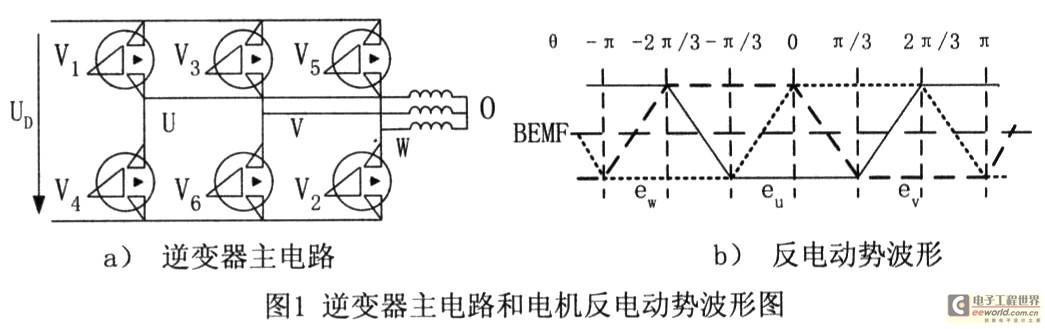
The main circuit of the inverter that realizes the electronic commutation and PWM control of the brushless DC motor is shown in Fig. 1a. Use two-by-two power supply method, that is, two power tubes are turned on every instant, and commutation is performed every 60 ° electrical angle, and each power tube is turned on 120 ° electrical angle. The conduction sequence of the power tube is: V6V1 → V1V2 → V2V3 → V3V4 → V4V5 → V5V6.
In a square-wave brushless DC motor, the back-EMF waveform of the stator winding (that is, the air-gap flux waveform) is a trapezoidal wave with positive and negative symmetry, as shown in Figure 1b. It can be seen from the figure that when the back electromotive force of the non-energized phase winding is detected to be zero, this is used as the starting point to lag the electrical angle by 30 °, which is the optimal commutation time. Therefore, as long as the zero crossing points of the opposite electromotive forces are measured, the six key position signals required by the three-phase motor can be obtained, and then the correct commutation of the stator winding can be realized. The neutral point 0 of the motor winding is generally not led out. It is difficult to directly measure the phase value of the winding's back electromotive force, and it is more convenient to measure the terminal voltage of the three-phase stator winding to ground. The midpoint of the terminal voltage (half the DC power supply voltage) and the zero-crossing point of the back-EMF are coincident in time, so 30 degrees of electrical angle after looking for the zero-crossing point of the back-EMF is equivalent to 30 degrees of electric angle.
2 Control system design
2. 1 hardware circuit design
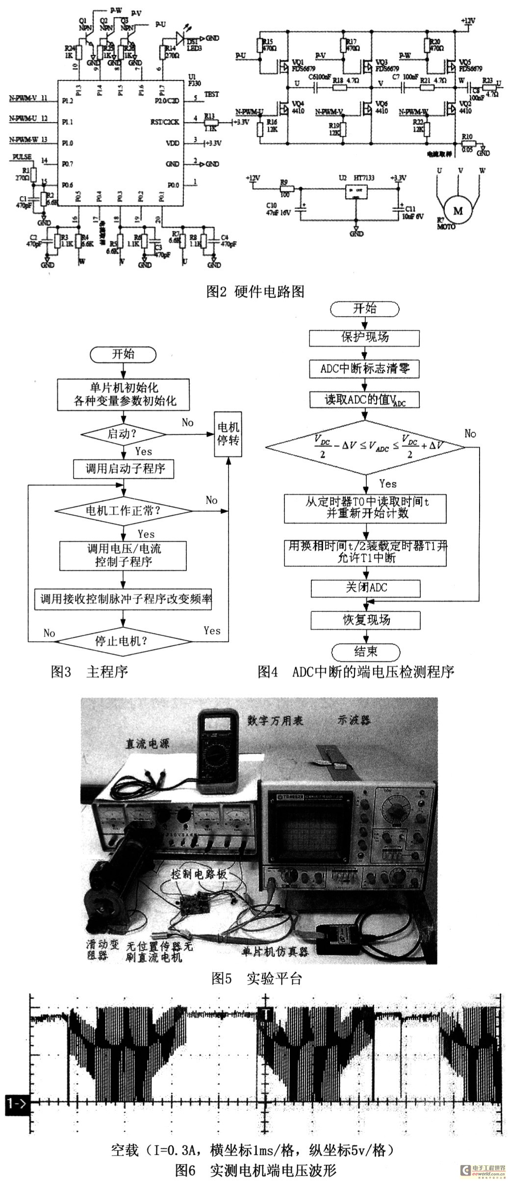
The hardware circuit diagram of the system is shown in Figure 2, which is composed of C8051F330 single-chip microcomputer, inverter bridge circuit, terminal voltage detection circuit, voltage regulator circuit and so on. The design of this circuit is very simple. Various components are packaged in a small patch, which is very suitable for a micro motor controller that is sensitive to cost and volume.
In the inverter bridge circuit, the upper arm is a P-type MOSFET device FDS6679, and the lower arm is an N-type MOSFET device M4410B, all of which are low-voltage driving devices. FDS66 79 is driven by an NPN transistor, and M441 0B is directly driven by the P1 port of the C8051F330 (P1 port is set as a push-pull output). The PWM control mode is set as follows: PWM is only applied to the lower end MOSFET of the half-bridge, while the upper end (diagonal) MOSFET of the commutation only performs commutation on-off control.
Detection of power supply voltage and current: when the UV phase is energized, the U-phase terminal voltage Uu is detected during the PWM turn-on period. Since the on-state voltage of the MOSFET is very small (less than 0.1V), the terminal voltage uu can be approximately regarded as the power supply voltage UD ; Sampling resistor is connected in series between the source of the lower bridge arm and the power supply ground, and the current value is obtained by detecting the resistance voltage through P0.4 port. The input signal is first amplified by an internal programmable gain amplifier and then A / D converted.
2.2 Software design
The software is mainly composed of initialization program, motor starting program, terminal voltage detection and commutation program, voltage and current protection program, operation control program and so on. There are four interrupts: PWM interrupt, ADC interrupt, T1 interrupt, T2 interrupt. Among them, the T2 interrupt implements the motor starting procedure, the PWM interrupt starts the ADC interrupt during the PWM turn-on, and the terminal voltage is detected during the ADC interrupt. When the back-EMF zero crossing is detected, the T1 interrupt is started to complete the commutation. The main program is shown in Figure 3.
2. 2. Initialization of 1G8051 F330
Due to the difference in internal resources between the C8051F330 microcontroller and the 8051 microcontroller, their initialization is different. There are two main differences: the configuration of the crossbar switch on the external pin; and the configuration of the system clock source. Considering that the user writes the initialization program very tediously, Silicon Labs has launched the C8051F microcontroller initialization code generation program software Config2Version 1.30. As long as the user clicks and selects with the mouse on the graphical interface, the initialization program of C8051F330 can be easily generated. Greatly speed up the user's development speed.
2.2.2 PWM wave output control
The programmable counter array (PCA) of C8051F330 is composed of a dedicated 16-bit counter / timer and three 16-bit capture / compare modules, which can exactly implement 3-way 8-bit PWM or 16-bit PWM function. The high byte PCAOH and low byte PCAOL of PCA's 16-bit counter / timer determine the frequency of the PWM wave. By changing the high byte PCAOCPHn and low byte PCAOCPLn of the capture / compare module, the duty cycle of the PWM wave can be changed.
2.2.3 Terminal voltage detection and commutation
Back-EMF commutation signal detection: The ADC is started during the PWM turn-on period, and the terminal voltage in the non-energized phase winding is detected, and its value is equal to half of the power supply voltage as the back-EMF zero crossing signal. Consider: a. The ADC detection time should be synchronized with the PWM, and the midpoint of the PWM turn-on time should be selected to avoid transient voltage noise in the switching state. b. The first few back-EMF sampling points after commutation should be discarded in the software, because the winding current will not be zero immediately after commutation, and it will drop to zero after a freewheeling process. The procedure is shown in Figure 4. Use timer 0 to record the time of continuous monitoring of the zero-crossing point of the two terminals, divided by 2 is the time of 30 ° electrical angle, load this time into timer 1, timer 1 triggers an interrupt after 30 ° electrical angle time , Call the commutation subroutine for electronic commutation.
3 Experimental results and conclusions
The experimental prototype uses a sensorless brushless DC motor produced by Changsha Fangyuan Model Factory, model 1208436, rated parameters, speed: 4100r / V, 2 pairs of poles, maximum current: 4A, internal resistance: 0.59Ω, no-load current: 0.3A. The experimental platform is shown in Figure 5.
When the power supply voltage is 10V, the PWM duty cycle is 20%, and no load, the terminal voltage waveform is shown in Figure 6. It can be seen from the figure that the commutation time is about 0.6ms, and the terminal voltage waveform is a better trapezoidal wave. According to the motor rated parameters, the commutation time is calculated as 0.609ms (60 ° electrical angle), which shows that the commutation time is more accurate. Experiments have proved that with the above control technology, the motor system starts smoothly without vibration and out-of-step phenomenon. At the same time, the system has the advantages of simple structure, miniaturization, low cost, reliable operation and good speed regulation performance.
SK6812 Digital LED Strip is one of single signal transmission full color led strip.
SK6812 is an intelligent internal control LED light source and each component is a pixel point.
Have same functions and same PCB With WS2812B, but difference is the SK6812IC can be inside and outside,Working Voltage is 5-24VDC. The Sk6812IC can be replace the WS2812B in some cases.
SK6812 Digital LED Strip
RGB CCT LED Strip,SK6812 LED Strip,SK6812 Digital LED Strip,Mini RGB LED Strip
SHEN ZHEN SEL LIGHTING CO.,LTD , https://www.sel-lighting.com