
Measure multiple parameters, accurate readings, and long battery life — these are the most important for wearable health devices.
Great changes have taken place since the first pedometer was launched 10 years ago. Initially, measurements only focused on the step counter function. The results of a decade of research have shown that walking 10,000 steps a day can maintain a balanced calorie intake and consumption. At the same time, wearable devices add other features and features such as heart rate, heart rate changes, body temperature and skin conductivity. Wearables were originally designed for sports and health purposes, but are now slowly entering the medical market. With this shift, we must rely more on the accuracy of the measurements and the length of the battery life. The longer a battery can keep the device running, the easier it is for the user.
This article introduces a new generation of wearable device products, including tips and tips on how to improve your system's reliability and energy efficiency.
PPG for heart rate measurementWhen it comes to good health, the most important organ in our body is the heart. It can be considered as the engine of the human body system. Without a well-functioning heart, we will face serious health problems. Monitoring heart function for this reason is a top priority. When the number of heart beats per minute exceeds the normal value, we have good reason to check our heart rate. In addition, we can get a lot of heart behavior information through the frequency of heart activity. When the body needs more activities, the heart rate is faster, bringing more nutrients and oxygenated blood to the cells. Continuous high heart rate and rapid heart rate changes are not good, which may indicate the presence of heart disease such as atrial fibrillation.
In addition to monitoring heart frequency, there is another parameter called heart rate variability (HRV). When people relax, their heart rate per minute is not fixed, and the heart rate will change slightly, within ±3 times per minute. This change indicates a state of relaxation. When people are nervous or frightened, the level of adrenaline in the body rises and the heart begins to beat with no change in frequency. It is therefore important to monitor the HRV parameters.
The classic method of acquiring cardiac signals is bioelectrical measurement electrocardiogram (ECG). However, it is not easy to integrate it into a wearable device.
The tendency to measure heart rate, in addition to the use of bioelectricity, can also be based on optical principles. This technology has been around for a long time and is called photoplethysmogram (PPG). PPG technology is mainly used in systems that measure blood oxygen saturation (SPO2) in blood. SPO2 measures the emission of two different wavelengths of light through a specific part of the body (usually a finger or earlobe), measuring the percentage of oxyhemoglobin and the total amount of hemoglobin. Because this technology can also measure heart rate, it is widely used in wearable devices, such as small wrist-worn devices, which, unlike bioelectrical measurements, can pick up heart rate using a single point measurement. Analog Devices' ADPD174 is an optical subsystem used to support these applications (see Figure 1).
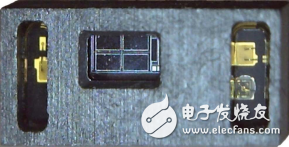
Figure 1. ADPD174 in a single package 6.5 mm & TImes; 2.8 mm optical system.
Reflection and transmissionMany people are familiar with SPO2 measurements, which can be achieved by attaching clips to the fingers or earlobe. Light is transmitted through a part of the body and the received signal is measured by a photodiode at the other end. We use this transmission technique to measure the amount of light that is received or not absorbed. This technology works best in terms of signal performance and power consumption. However, integrating transmission measurements in a wearable system is also not an easy task, as comfort is critical for wearable systems. Therefore, reflection measurements are more common. In a reflective optical system, light is sent to the surface of the tissue, a portion is absorbed by the red blood cells, and the rest of the light is reflected back to the surface of the tissue, as measured by the light sensor. In a reflective system, the received signal does not exceed 60 dB, so we need to pay more attention to the electrical and optical aspects of the transmit and receive signal chains.
Electronic and mechanical challengesDuring the beating of the heart, the blood flow changes, causing the reflected light to be scattered. The wavelength of the light used to measure the PPG signal will vary with various factors—the first is the type of measurement. In this article, we limit the measurement to heart rate and its range of variation. For this measurement, the required wavelength depends not only on the measured body position, but also on the associated blood perfusion level, tissue temperature, and tissue tone. Generally for wrist-worn devices, the artery is not at the tip of the wrist, and you need to detect the pulsating component from the veins and capillaries below the surface of the skin. Using green light in these applications allows us to receive better. In areas with plenty of blood, such as the arms, temples, or ear canal, red or infrared is more effective, it can penetrate deeper into the tissue—especially for wearable applications where battery power and size are always a problem, red Light or IR LEDs offer the added advantage of requiring only a low forward voltage. For applications that use coin-cell batteries, these LEDs can be driven directly from the battery voltage.
2 When each μA plays its role!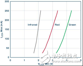
Figure 2. Required LED forward voltage and LED current.
Unfortunately, green LEDs require a higher forward voltage, so additional boost converters are needed, which can adversely affect the total power consumption of your system. Figure 2 shows the forward voltage required for different color LEDs as a function of current. If a green LED is still required, the ADP2503 buck/boost converter can help support higher LED forward voltages with input voltages up to 5.5 V or as low as 2.3 V.
When weighing the considerations, such as sensor position and LED color, the next step is to choose the most appropriate optical solution. There are many options for analog front ends, discrete or fully integrated, as well as a large selection of light sensors and LEDs. To minimize design effort and time to market, ADI has built a fully integrated optical subsystem for reflective optical measurements. The ADPD 174 contains all the components needed for optical measurements. Figure 3 shows the block diagram of the ADPD174 subsystem. The module measures 6.5 mm &TImes; 2.8 mm, which is very attractive for wearable systems.
The module uses a large photodiode, two green LEDs and an IR LED. The onboard mixed-signal ASIC includes an analog signal processing module, a SAR ADC, a digital signal processing module, an I2C communication interface, and three programmable LED current sources.
The system drives the LED and uses its 1.2 mm2 photodiode to measure the corresponding optical return signal. The biggest challenge in measuring PPG with wearable devices is to overcome the interference of ambient light and motion-generated artifacts. Ambient light can have a significant impact on the measurement results. Sunlight is not difficult to suppress, but the special light from fluorescent and energy-saving lamps contains AC components that are difficult to eliminate. The ADPD174 optical module features two levels of ambient light suppression. After the light sensor and input amplifier stage, an integrated bandpass filter followed by a synchronous demodulator provides best-in-class ambient light suppression and up to 100 kHz DC interference. The ADC has 14-bit resolution and up to 255 pulse values ​​for a total of 20-bit measurement resolution. Accumulating multiple samples enables resolutions of up to 27 bits.
For example, the ADPD 174 operates in two independent time slots to measure two different wavelengths and can execute the results in sequence. During each time slot, a complete signal path is performed, starting with LED excitation, then capturing the optical signal and processing the data.
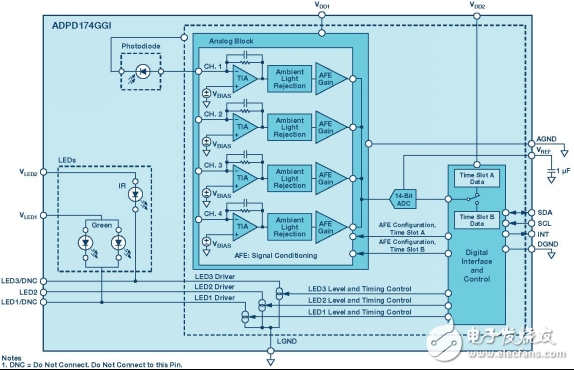
Figure 3. Block diagram of the ADPD174 optical subsystem.
Each current source is capable of driving LEDs with currents up to 250 mA. Innovative LED pulse control keeps the average power consumption low, which helps to a large extent save system power and battery life.
The advantage of this LED driver circuit is that it is dynamically scalable. Many factors can affect the signal-to-noise ratio (SNR) of the receiving optical signal, such as skin tone or hair between the sensor and the skin, which can affect the sensitivity of the receiving end. Therefore, the excitation LED configuration is very convenient and can be used to build an adaptive system. All timing and synchronization are handled by the analog front end, so there is no added overhead for the system microprocessor. Under normal circumstances, you can use the ADPD174 to perform reliable heart rate monitoring at approximately one milliwatt power level. To find this operating point, we can tune the gain of the Transimpedance Amplifier (TIA) and combine it to set the maximum LED peak current. After optimizing the LED current and TIA gain, we can increase the number of LED pulses to get more signals. Note that increasing the peak current of the LED increases the SNR proportionally, while increasing the number of pulses by n times only results in an improvement in the SNR of the n-square root (√n).
Finding the best settings for a heart rate device is also largely dependent on the user. The skin color of the user as well as the location of the device, temperature and blood flow can affect the signal strength. When calculating power consumption, the optical front end can be seen as two independent power factors, IADPD and ILED. IADPD is the current consumed by the input amplifier stage, ADC, and digital state machine. These power values ​​are highly dependent on the sampling rate of the ADC. The LED current ILED will vary with the skin color of the human body and the position of the sensor on the body. For darker skin, more LED current is needed, and more LED current is needed when the sensor is in a position where the body's blood flow is low. The average LED current varies with the LED drive pulse width, the number of pulses, and the ADC sampling time. The average LED current is the maximum LED current multiplied by the pulse width and the number of pulses. This can be thought of as a time slot, repeated each time a new sample is obtained. The pulse width can be as narrow as 1 μs.
To achieve good heart rate measurement on the wrist, when using two pulses with a width of 1 μs, the LED peak current needs to reach 125 mA. For a 100 Hz sampling frequency, the average LED drive requires 25 μA. When we increase the average AFE current of 250 μA, the optical front end consumes 275 μA (@ 3 V = 825 μW).
Other mechanical challengesWe discussed one of the challenges in designing optical systems: ambient light interference. Another big problem is the solution to internal light pollution problems in reflective mode optics. In a perfectly designed system, all of the light from the LED is sent to the tissue, and only the reflected light is visible and measured by the light sensor. But in reality, the LED light is reflected by the transparent window on the outer casing and returned directly to the light sensor without penetrating the green light path (see Figure 4).
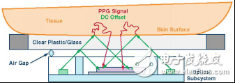
Figure 4. Description of internal light pollution.
This ILP effect causes a dc offset and will limit the AC component of the signal, also known as the modulation index (MI). In fact, MI is the only signal we are interested in. ILP can be solved by a separate window - however, achieving mass production is very difficult and expensive. ADPD174 can solve this problem. It has a specially designed housing that reduces ILP behavior without the need to separate the transparent window on the housing. Figure 5 shows an improvement in the relationship between ILP reduction and LED current as a function of ADPD174 compared to its predecessor. This is another advantage over other discrete or integrated devices on the market.
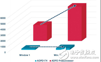
Figure 5. ADPD174 ILP affects its predecessor.
Total power consumption of your systemIn optical systems, in addition to illumination interference, it is also necessary to eliminate interference caused by motion. Exercise can affect the overall performance of the wearable system, resulting in optical reading errors due to movement, mechanical connections, or changes in contact with the tissue. Therefore, it is important to measure the motion of the device and compensate for the effects of interference. The ADI ultra-low power 3-axis ADXL362 MEM sensor fully supports these needs. The sensor measures all three axes and integrates a 12-bit SAR ADC to achieve a sensitivity of only 1 mg per LSB and enables communication via a digital SPI interface. Power consumption is proportional to the ADC sample rate, with a data output rate of 100 Hz per axis and a sensor power consumption of only 1.8 μA. It is available in a 3 mm × 3 mm package. - Following the ADXL362, a new generation of products is still under development, using only a quarter of the ADXL362 PCB area.
Missing "adhesive"!So far, we have discussed the various sensors needed to build wearable health devices that monitor heart rate and heart rate changes. What is missing is the core of the system, connecting all of these sensors together, running the required software algorithms and storing, visualizing or transmitting the results. ADI's new ADuCM3027/ADuCM3029 Cortex®-M3 processor supports all of these needs. It is an ultra-low-power, mixed-signal microcontroller that handles the power consumption of the function "38 μA per MHz. The processor has a clock frequency of up to 26 MHz and can operate in four different power modes, see Table 1.
Table 1. Power Mode ADuCM3027/29
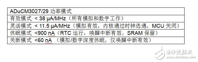
The mixed-signal front end includes a 12-bit SAR ADC, a reference buffer, and a temperature sensor. The board has 128 kB or 256 kB of onboard flash, 4 kB cache and 64 kB of SRAM. Great efforts have been made to prevent unauthorized users from reading device content through an external interface. This is of great value to device manufacturers in protecting their code and algorithms. Finally, the ADuCM302x operates from a single operating voltage of 1.8 V to 3.6 V. The 1.2 V core voltage can be generated by an on-board LDO or its more efficient switched-capacitor buck converter.
To wirelessly upload measurements to the host processor, you need to consume a lot of power from the system. Pre-processing measurements will help reduce the amount of data that needs to be transferred. This can save more power.
Let your health equipment teach yourselfIn the previous paragraphs, you learned that ADI places a high priority on sensor and mixed-signal solutions with a focus on high performance and low power consumption. These chips and subsystems can be used to create equipment for the health and sports and healthcare markets that can run for long periods of time with a single button battery. The challenge is always to build a system with high enough performance while minimizing power consumption. Adaptive algorithms help improve overall performance and find the most efficient system low-power location. Each time you use the device, you can change the settings slightly to achieve the relevant HRM accuracy for optimal SNR performance and power consumption.
About the AuthorJan-Hein Broeders is the Healthcare Business Development Manager for ADI's Europe, Middle East and Africa operations. He works closely with the healthcare industry to turn their current and future needs into solutions based on ADI's market-leading linear and converter technology and digital signal processing and power products. Jan-Hein began his career in the semiconductor industry 20 years ago as a Burr-Brown analog field application engineer responsible for Benelux and Scandinavia. Five years after Texas Instruments acquired Burr-Brown, he joined Analog Devices as the Philips Global Field Application Engineer (FAE). Since 2008, he has been working on the current health care business development work. He holds a bachelor's degree in electrical engineering from the University of Den Bosch in the Netherlands.
All our items Suitable for space like meeting room, living room as well as restaurant, leisure club,office etc;
And all are packed in singel neautral box safely, mass production in carton case approved by drop test. We can make custom logo and box for bulk cargos. Please click to contact us freely if you have the query. We have different shipping options for you: Express, Air, Sea. Please choose your favorite way, or you can also refers to our recommendation.
We have our own Control systems: Shorten lead times at low cost with responsive production planning and with many years experience of producing products.
We could provide OEM / ODM service for all kinds of customers. Our professional support team will service online 24 hours for customers.
We have a very strong quality control Samples are always available for checking quality and Efficient Logistics.
Professional Design Team: artwork/ Instruction manual/ product design according to customer's requirements.
Air Aroma Diffuser,Aroma Bloom Diffuser,Wireless Oil Diffuser,Aroma Essential Oil Diffuser
KIWA ELECTRONIC (HK) INDUSTRIES CO.,LTD , https://www.kiwahk.com