In a single-chip microcontroller application system, the I/O port is commonly used to implement a self-shutdown function, which means completely cutting off the power. Typically, an electronic switch controlled by the MCU is used for this purpose. However, when the MCU is powered down, the system loses power, and the I/O pin that was previously high will eventually drop to a low level. But there's a problem here.
When the electronic switch is turned off, due to the presence of the power supply filter capacitor, the voltage of the microcontroller system doesn't immediately drop to zero—it gradually decreases. At some point, the voltage may fall below the normal operating level, causing the MCU to enter a reset state, program failure, or an undefined state. During this transition, the I/O pins might momentarily return to a high level, which could inadvertently turn the electronic switch back on, leading to an unstable power state.
To solve this issue, we can take advantage of the fact that the minimum operating voltage of a general-purpose microcontroller is lower than its normal operating voltage. By designing the shutdown circuit accordingly, we ensure that the turn-on voltage of the electronic switch is higher than the minimum operating voltage of the MCU. This way, when the MCU is running normally, the control voltage is high enough to keep the switch on. But during power-off, as the voltage drops, the I/O pin’s high level is no longer sufficient to maintain the switch in the conducting state, thus ensuring a complete power cut.
The circuit works as follows: When the system is turned off, pressing S1 turns on Q2. Once the MCU starts up, it sets the POWER output to a high level, which turns on Q1 and keeps Q2 conducting. When the system is shut down:
1. **Software Shutdown**: The MCU’s POWER pin goes low, turning off Q1, which in turn turns off Q2, cutting the power. This method is often used for delayed shutdown, such as in digital multimeters.
2. **Manual Shutdown via S1**: Pressing S1 sends a low signal through D3 to the MCU’s ON-OFF pin. The MCU detects this and initiates a software shutdown as described above.
D3 serves as an isolation diode to prevent the MCU’s ON-OFF pin from being pulled low when the system is off, which could accidentally turn Q2 back on. The POWER pin is the output from the MCU, where a low level corresponds to 0V, and a high level matches the supply voltage. The ON-OFF pin is used by the MCU to monitor the state of S1. If S1 isn’t used, this pin can be repurposed for other functions.
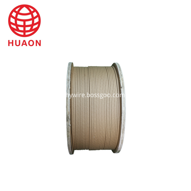
Paper Covered Flat Aluminium Wire
|
About Paper Covered Flat Aluminium Wire
|
Paper wrapped winding wire is made up of bare from oxygen free Copper Rod or electrical aluminum rod by drawing or extruding processing and wrapped by insulation materials.paper covered single wire , with insulation wrapping in the outside layer
As per Conductor Material:Copper , aluminum
As per Inner Conductor: Paper wrapped bare
Insulation thickness:Double paper covered (DPC) orTriple Paper Covered (TPC) ,According to Customer`s requirements
Packaging DetailsInner packing : Wooden bobbin
Outer packing : Wooden pallet and stretch film
Or according to our custormers' requirements

Conductor of Paper wrapped wire
Bare Wire Round Wire:Φ1.00 mm-Φ5.00 mm
Rectangular Wire thickness a:1.00 mm-5.60 mm
Width b:2.00 mm-16.00 mm
Conductor of Composite wires
Max wrapping layers once: 24 layers for Paper Covered Wire
4 layers per wire and 16 layers outside for composite wires
We could offer products of special requirements on conductor size, insulation layer thickness, or wire number of the composite.
Electrical Wire,Paper Covered Flat Aluminium Wire,Covered Magnet Aluminum Wire,Covered Magnet Aluminum Winding
HENAN HUAYANG ELECTRICAL TECHNOLOGY GROUP CO.,LTD , https://www.huaonwire.com

