
**1. Introduction**
In today's society, with the rapid development of the economy, people's living standards have significantly improved. However, this progress has also led to an increase in obesity and related health issues. As a result, more attention is being paid to health and fitness. Among various forms of exercise, walking has become one of the most effective and accessible methods to maintain good health. Walking not only helps improve cardiovascular function but also reduces stress and enhances overall well-being.
To make it easier for individuals to monitor their physical activity, pedometers have become increasingly popular. These devices are designed to count the number of steps taken throughout the day, helping users stay motivated and track their progress. Walking regularly can lower blood pressure, reduce cholesterol levels, and help manage weight by decreasing the load on the heart.
Modern pedometers, especially those based on single-chip microcomputers, offer high accuracy, reliability, and ease of use. They provide real-time feedback, allowing users to keep track of their daily movement. This makes them an essential tool for anyone looking to lead a healthier lifestyle.
**2. Overall Design**
The pedometer system consists of several key components: an oscillation circuit, a reset circuit, a display circuit, and a button circuit. It is powered by a battery, making it portable and convenient for everyday use. The system architecture is illustrated in Figure 1, showing how each component interacts to ensure accurate step counting and display.
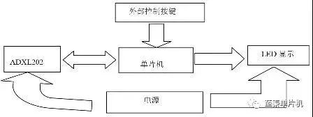
*Figure 1: System structure diagram*
**3. Hardware Design**
**3.1 Oscillation Circuit**
The oscillation circuit is a critical part of the microcontroller unit (MCU), specifically the AT89C51. It is composed of an inverting amplifier, a crystal oscillator, and two ceramic capacitors. The capacitors serve as compensation elements, ensuring stable frequency output and improving the performance of the oscillator. A properly functioning oscillation circuit is essential for the MCU to operate correctly. If the oscillator fails or operates irregularly, the system may experience timing errors, which can affect communication and overall functionality.
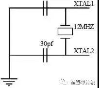
*Figure 2: Oscillation circuit*
**3.2 Reset Circuit**
To ensure the stability and reliability of the microcontroller system, a reset circuit is necessary. The primary function of the reset circuit is to perform a power-on reset. When the power supply reaches the required voltage range (4.75–5.25V), the reset signal is released, allowing the microcontroller to start its normal operation. During the power-up process, the reset pin must remain high for at least 10 milliseconds to ensure a reliable reset.
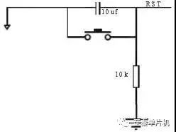
*Figure 3: Reset circuit*
**3.3 Display Circuit**
This design uses a 4-digit LED common cathode display to show the number of steps. Each digit is made up of seven segments, with an additional decimal point segment in some cases. The LEDs are controlled using segment codes that determine which segments light up to form specific numbers or characters. The cathodes of the LEDs are connected together, and the anodes are controlled individually to display different digits.
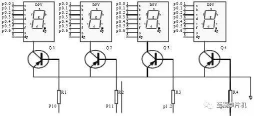
*Figure 4: Display connection circuit*
**3.4 Button Circuit**
Instead of using a sensor, this design simulates the step-counting process through a button. Each time the button is pressed, it represents one step. This method is used for demonstration and testing purposes. The circuit is shown in Figure 5.
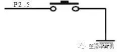
*Figure 5: Button circuit*
**3.5 ADXL202 Sensor Circuit**
For more accurate step detection, the ADXL202 sensor module is used. This accelerometer detects motion and provides data to the microcontroller, which processes the information and updates the step count accordingly. The sensor circuit is shown in Figure 6.
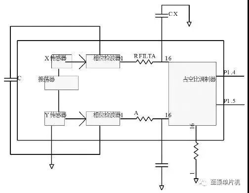
*Figure 6: ADXL202 sensor module circuit*
**4. System Software**
The software of the pedometer is responsible for processing the signals from the sensor or button and updating the display. When a step is detected, the system increments a counter and displays the result. The microcontroller also manages the reset function, which clears the counter when needed. The overall system flow is illustrated in Figure 7.
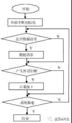
*Figure 7: System flow chart*
**5. Software Simulation**
In the simulation, the button K1 is connected to the P4.4 port of the microcontroller. When pressed, it generates an electrical signal that is processed by the microcontroller, which then updates the LED display. The simulation results are shown in Figure 8, demonstrating the functionality of the pedometer.
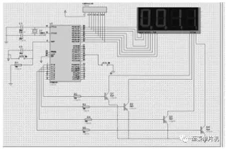
*Figure 8: Simulation renderings*
**6. Conclusion**
This project presents a complete design of a pedometer system, including the microcontroller, display, input interface, and real-time monitoring features. Through careful hardware design and software implementation, the system was successfully simulated and tested. The final product offers an efficient and user-friendly way to track daily physical activity, promoting a healthier lifestyle.
LVDS Automotive High Frequency Cable Assembly
Lvds Automotive High Frequency Cable Assembly,Electronic Components Connectors,Electronic Connectors,Electronics Connectors
Dongguan Zhuoyuexin Automotive Electronics Co.,Ltd , https://www.zyx-fakra.com