
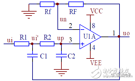
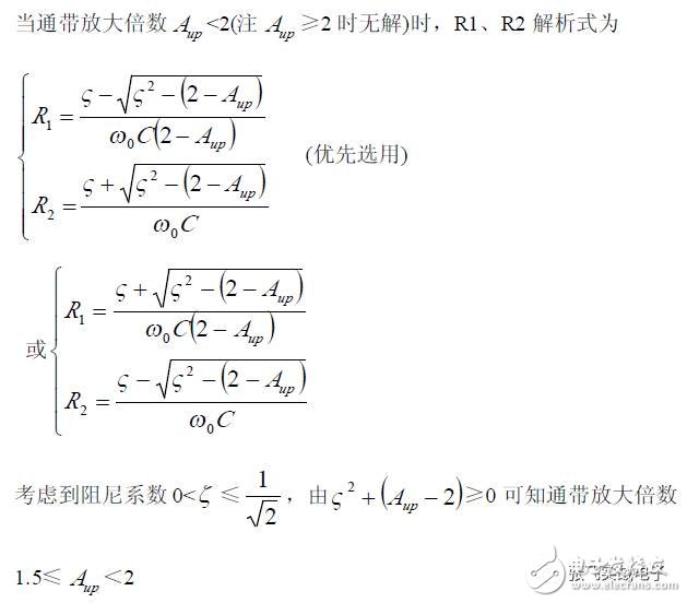
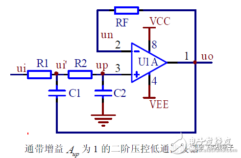
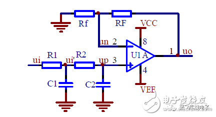
1. Second-Order Voltage-Controlled Low-Pass Filter
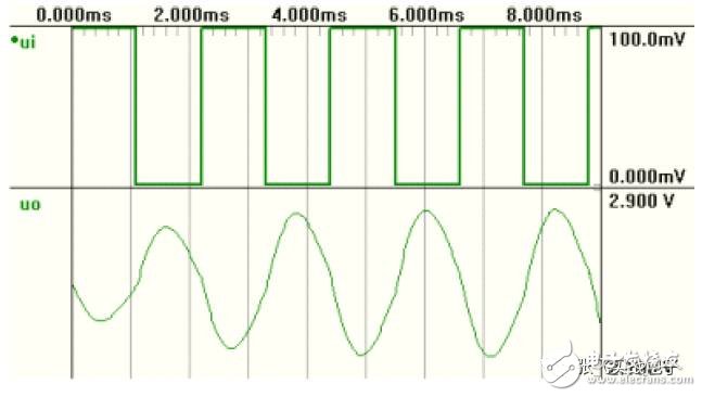
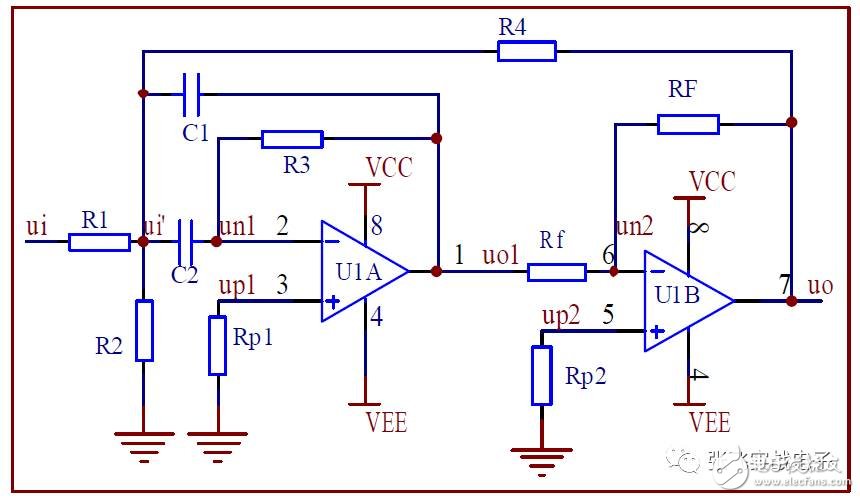
The second-order voltage-controlled low-pass filter circuit is illustrated in the figure. R1, C1, R2, and C2 form two first-order low-pass filters individually, but C1 is connected to the output terminal to introduce positive voltage feedback, thereby creating a voltage-controlled filter.
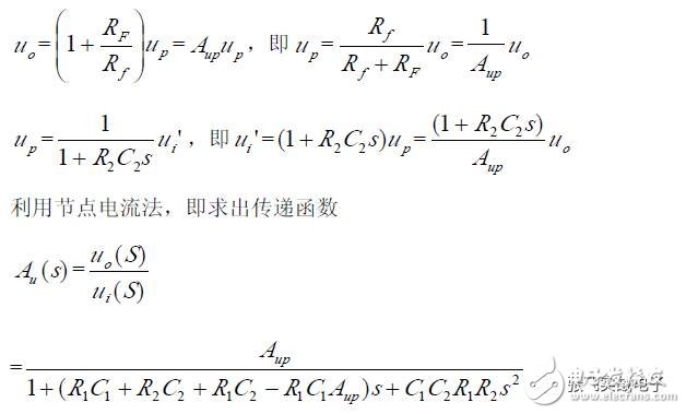
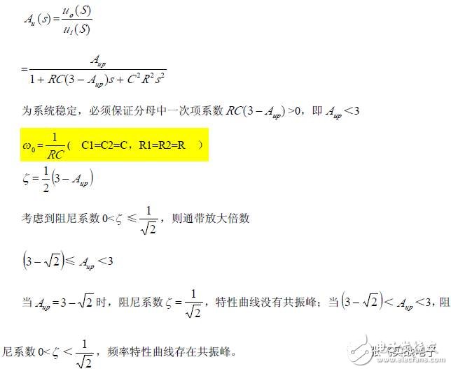
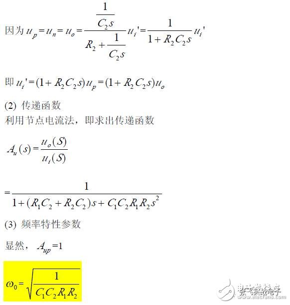
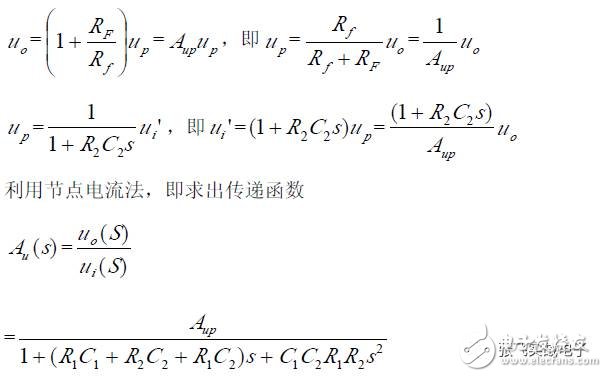
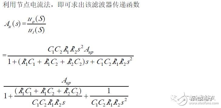
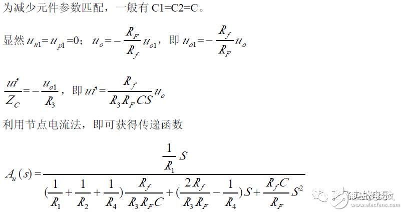
(1) Transfer Function
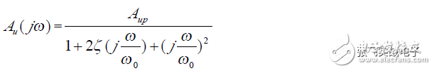
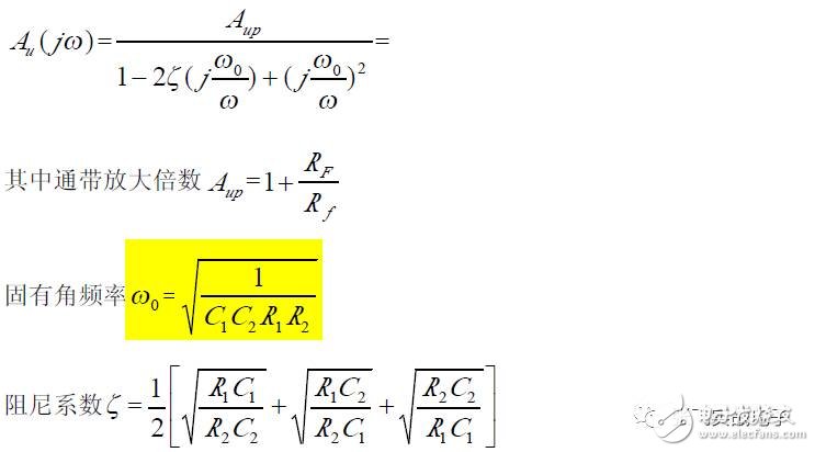
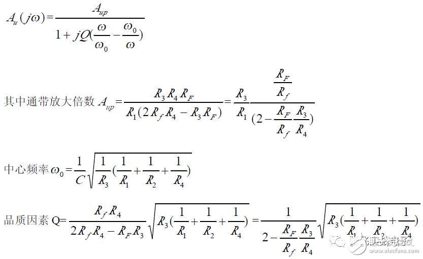
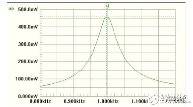
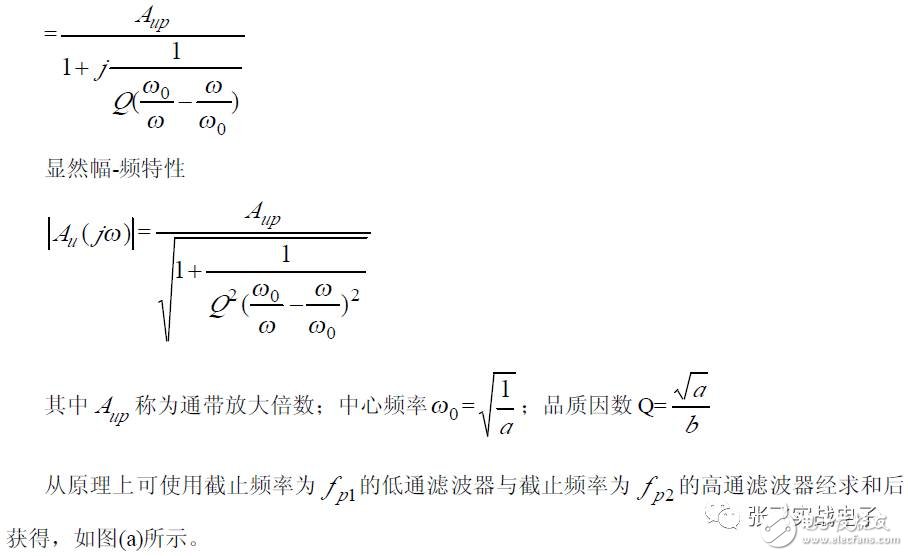
(2) Frequency Characteristics
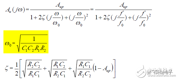
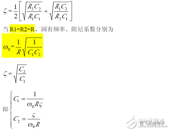
It can be observed that the low-pass filter is characterized by the damping coefficient ζ being determined by the ratio of resistors R1, R2, C1, and C2; and the natural frequency ω₀ is related to the specific values of R1, R2, C1, and C2, meaning that ω₀ and ζ are independently adjustable and do not interfere with each other.
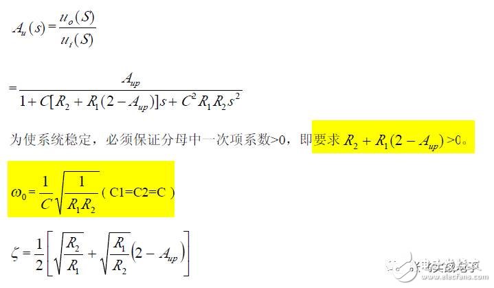
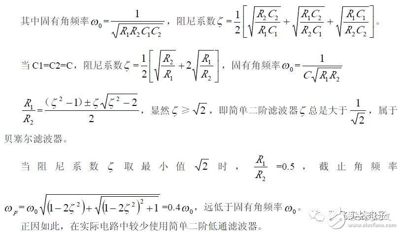
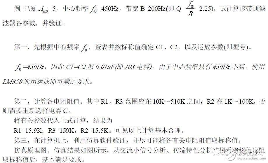
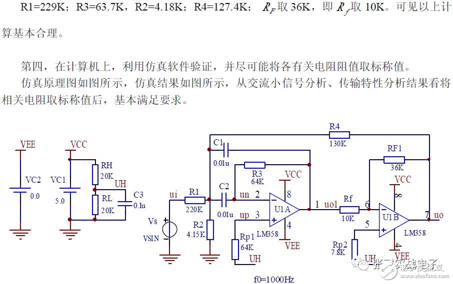
(3) Parameter Selection
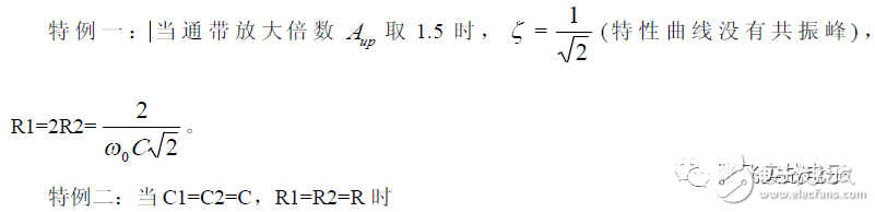
To facilitate parameter matching, considering the small nominal capacitance values, it is common to choose C1 = C2 = C. The specific natural frequencies ω₀ and ζ are then adjusted by selecting different R1 and R2 values.
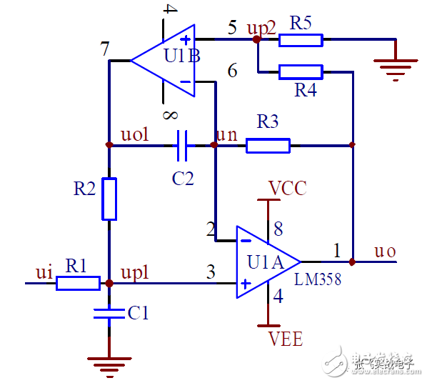
2. Unit Gain Second-Order Voltage-Controlled Low-Pass Filter
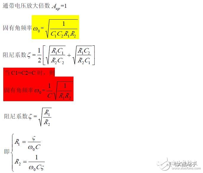
For the second-order voltage-controlled low-pass filter, when the passband amplification factor A_up = 1 (unit gain), the circuit becomes as shown in the figure, where RF = R1 + R2.
(1) Basic Relationship
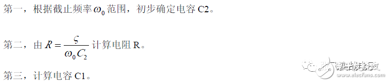
(4) Parameter Selection
In cases where the natural frequency ω₀ and the damping coefficient are known, the design steps are as follows:
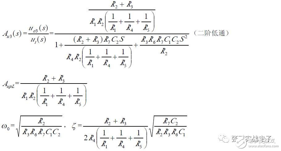
3. Second-Order Low-Pass Filter
(1) Transfer Function
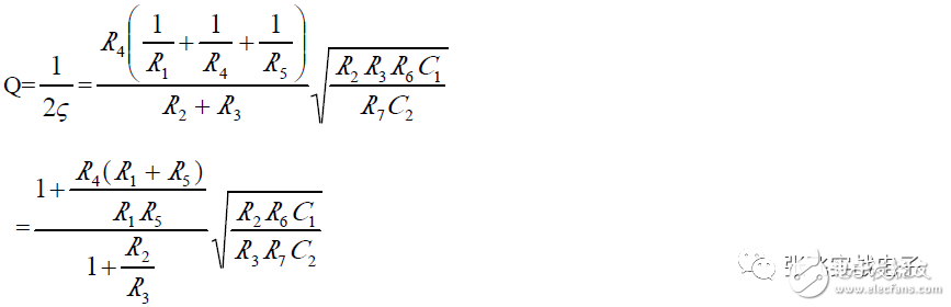
(2) Frequency Characteristics
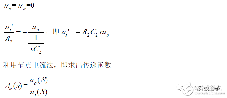
4. Infinite Gain Multiplicative Feedback Low-Pass Filter
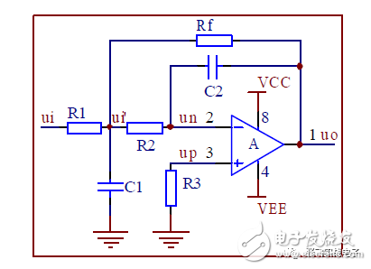
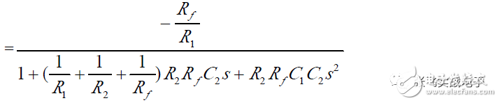
(1) Transfer Function
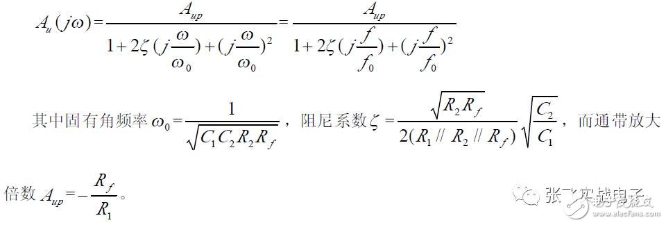
(2) Frequency Characteristics
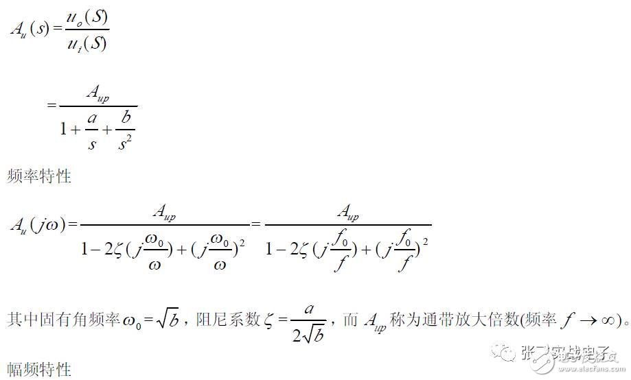
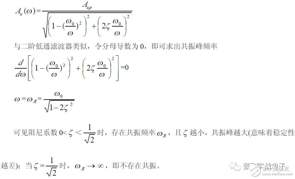
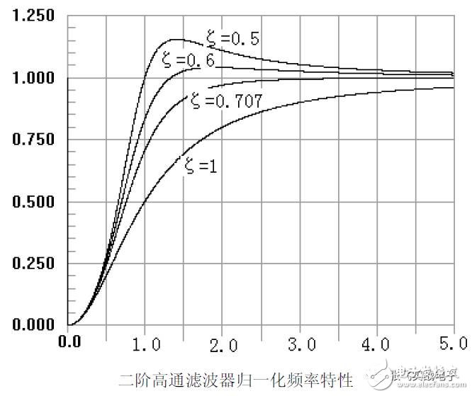
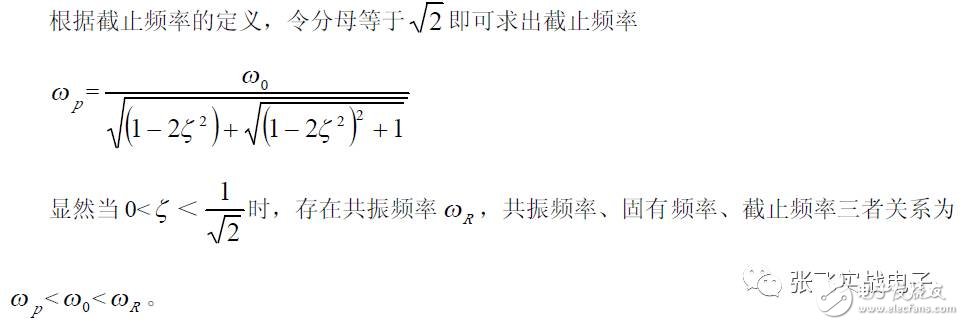
General form of the second-order high-pass filter transfer function
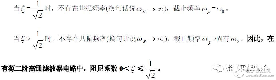
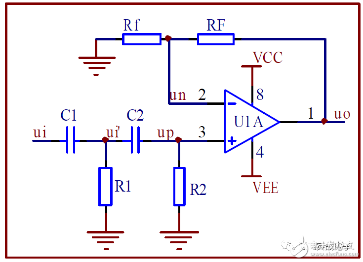
1. Second-Order High-Pass Voltage-Controlled Filter
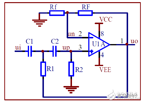
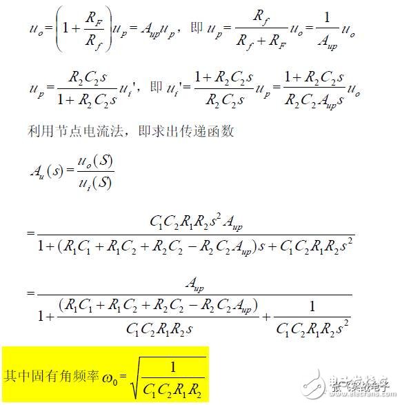
(1) Transfer Function
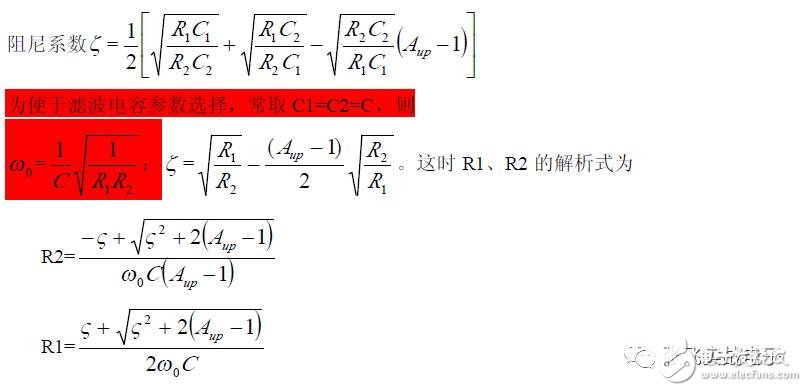
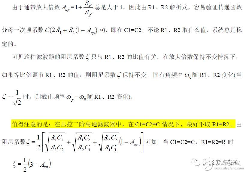
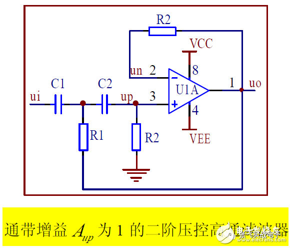
2. Voltage-Controlled High-Pass Filter with 2 Gains up A
When the passband amplification factor A_up = 1, the op amp is connected as a voltage follower, as shown.
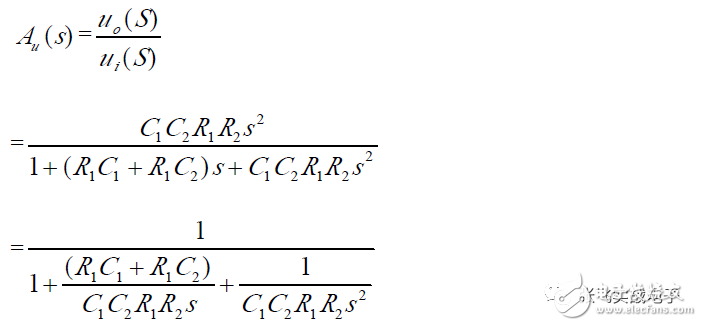
(1) Transfer Function
(2) Frequency Characteristics
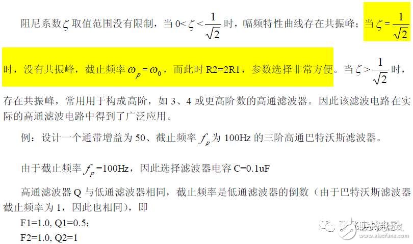
3. Infinite Gain Multi-Feedback High-Pass Filter
This circuit can operate on dual power supplies or single power supply, making it widely used.
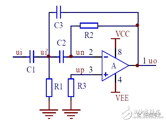
(1) Transfer Function
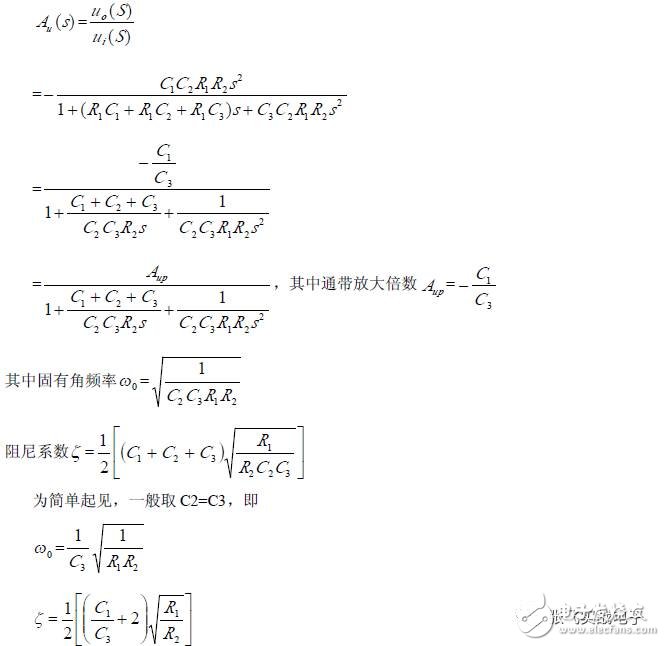
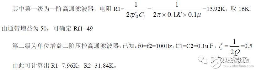
(2) Design Steps
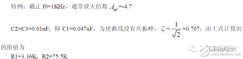
First, based on the cutoff frequency, initially identify C3; C1 is determined according to the passband gain A_up (Note: capacitors C1 and C3 take certain nominal values).
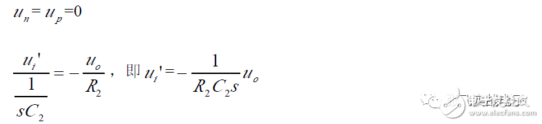
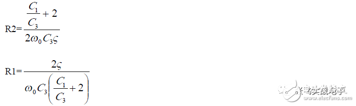
Second, once C1 and C3 are determined, when the natural frequency ω₀ and the damping coefficient are known, the resistor values R1 and R2 are determined using the following analytical expressions.
3. Second-Order High-Pass Filter
(1) Transfer Function
(2) Frequency Characteristics
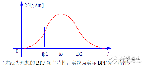
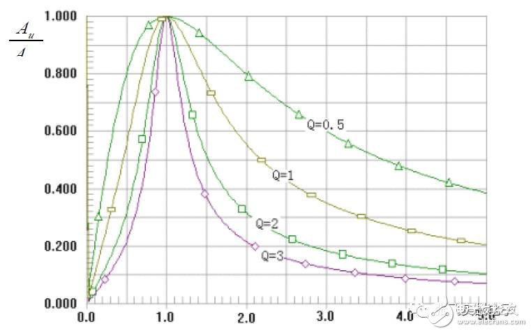
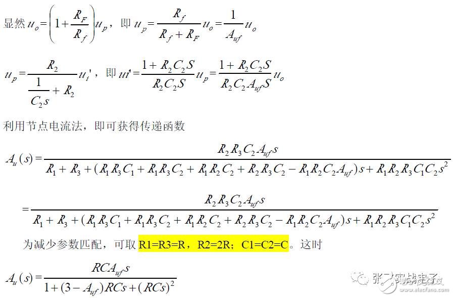
A bandpass filter (BPF) allows signals within a specific frequency range to pass through while significantly attenuating signals below f_p1 or above f_p2. Its amplitude-frequency characteristics are shown in the figure.
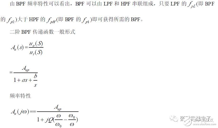
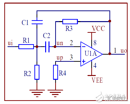
1. Second-Order Bandpass Filter
The simple second-order bandpass filter circuit is shown in the figure, where R1 and C1 form a low-pass filter, and C2 and R3 form a high-pass filter.
(1) Transfer Function
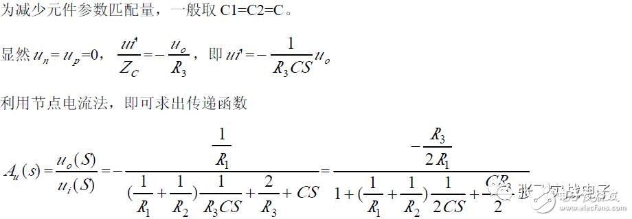
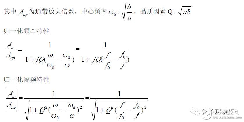
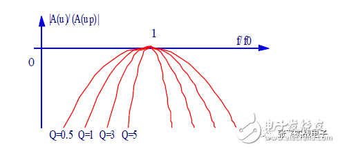
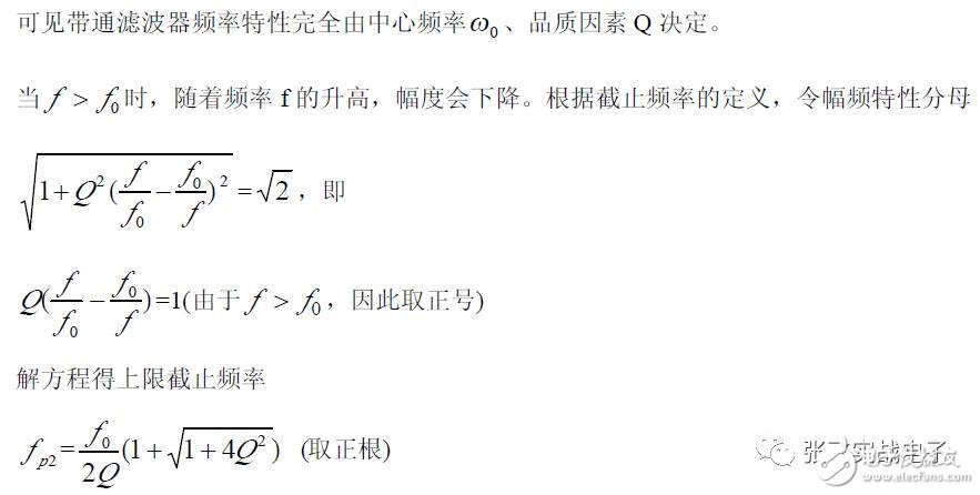
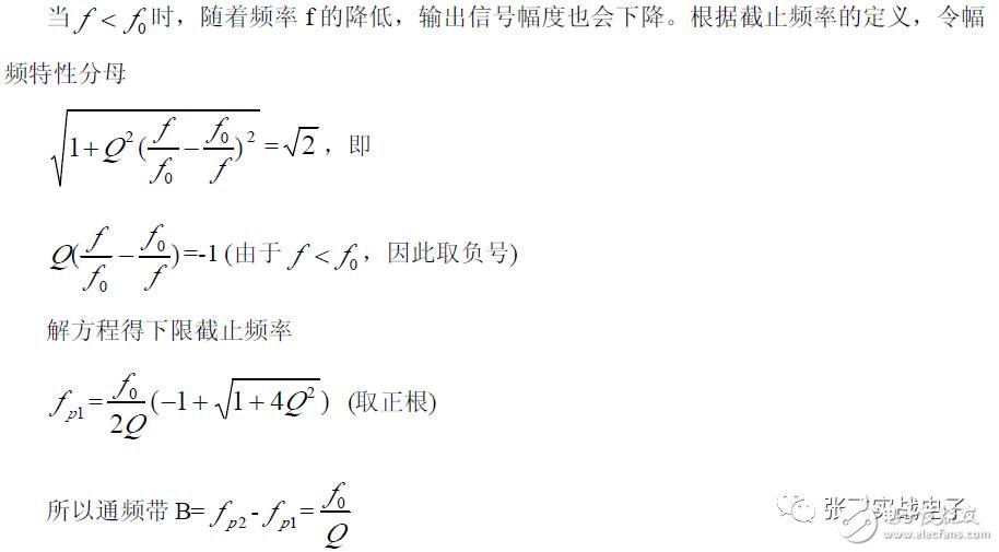
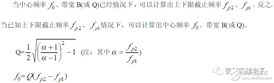
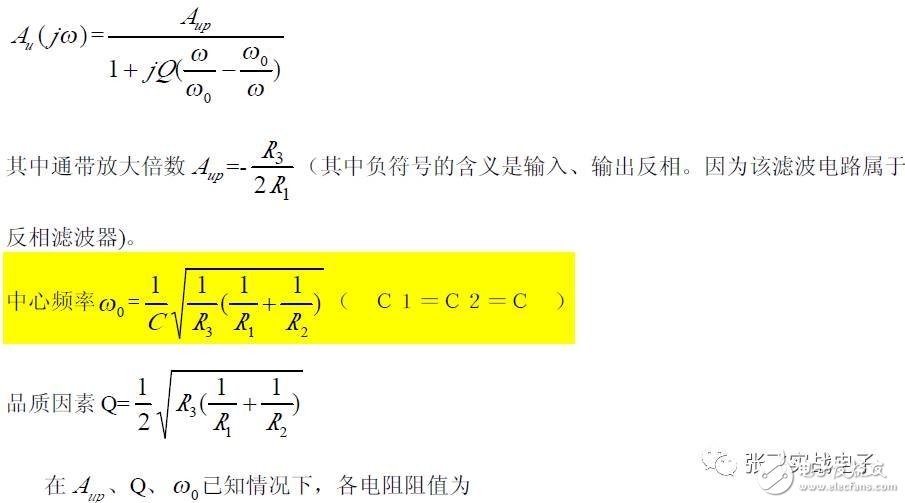
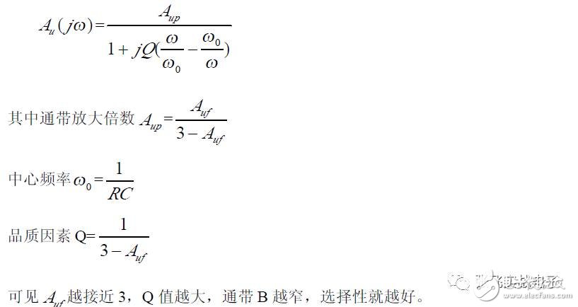
(2) Frequency Characteristics
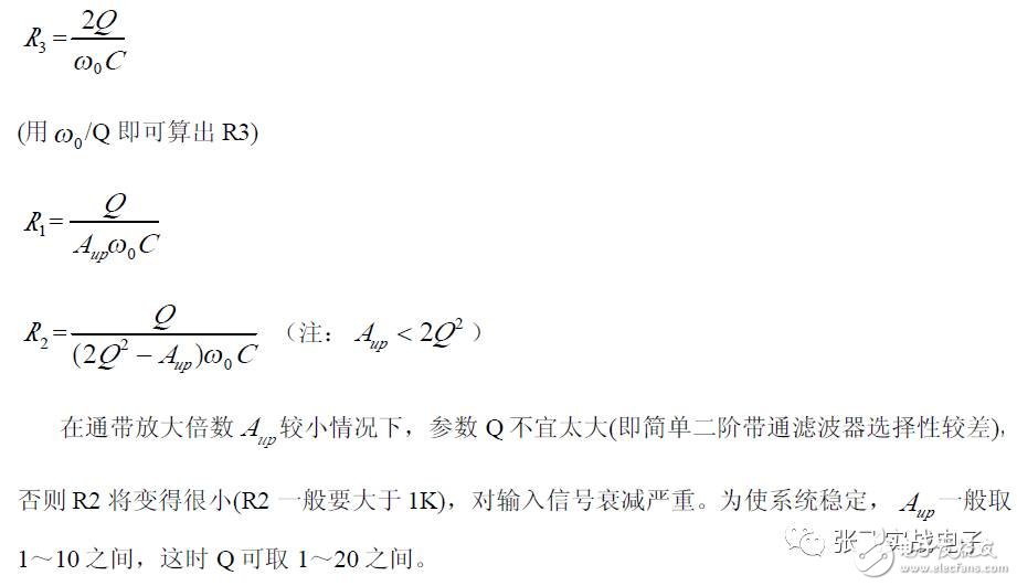
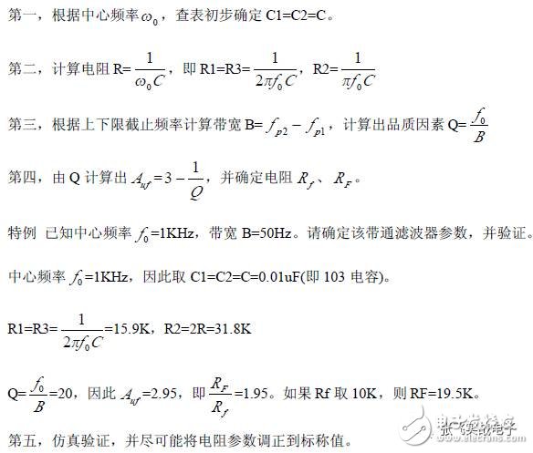
(3) Design Steps
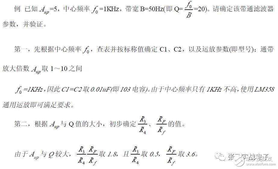
The following is a concrete example to explain the design process of this type of bandpass filter circuit.
This circuit requires few components, can operate from dual power supplies, or from a single supply (with a bias potential of 1/2Vcc), so it is widely used in single-supply systems. However, the quality factor Q cannot be too high, and this circuit is typically used in bandpass filters with a large bandwidth B (i.e., a small Q value).
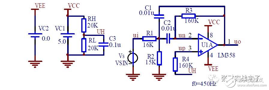
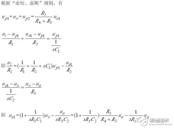
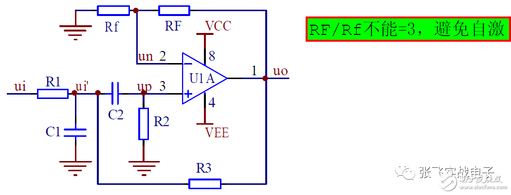
2. High Q Value Second-Order Bandpass Filter
The high-Q value second-order bandpass filter circuit is shown in the figure. The circuit can work with dual power supplies or single-supply operation and is easy to use in single-supply systems.
Since the Q value can be made larger, it is particularly suitable for point frequency filtering.
(1) Transfer Function
(2) Frequency Characteristics
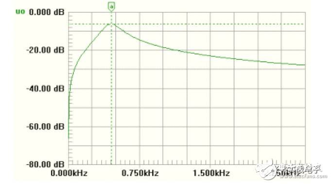
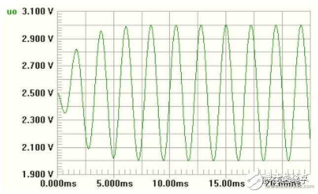
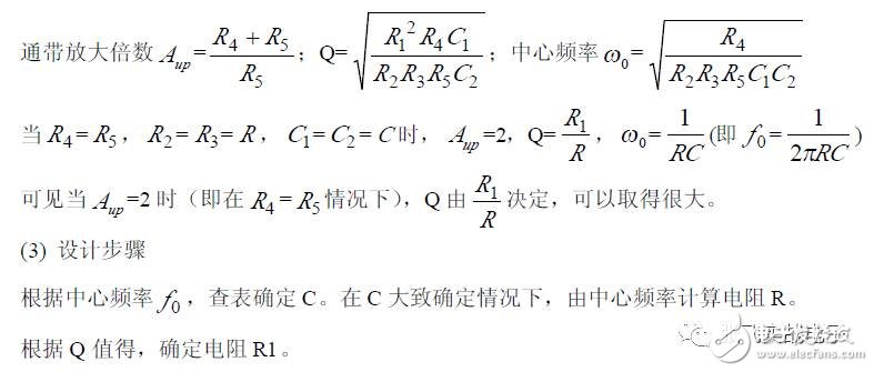
(3) Design Steps
The following is a concrete example to explain the design process of this type of bandpass filter circuit.
3. High Q BPF Composed of Dual Op Amps
A high Q value BPF (DABPF) circuit composed of dual op amps is shown. Since the circuit uses few components, a very high Q value can be achieved when the passband amplification A_up is fixed at 2, making it a commonly used BPF circuit.
(1) Transfer Function
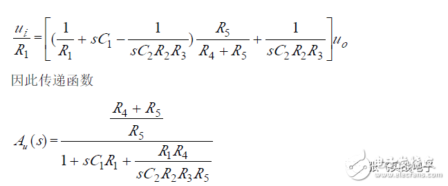
(2) Frequency Characteristics
Compared with the standard second-order BPF transfer function, the following parameters can be obtained:
4. Second-Order Voltage-Controlled Bandpass Filter
The second-order voltage-controlled bandpass filter is shown in the figure, where R1 and C1 form a low-pass filter, R2 and C2 form a high-pass filter, and positive voltage feedback is introduced through R3 to create a voltage-controlled bandpass filter.
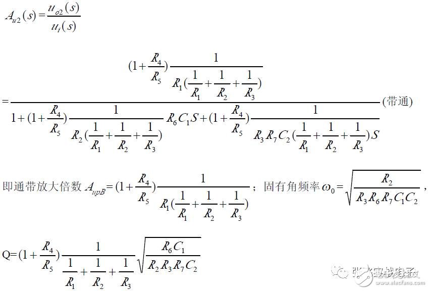
(1) Transfer Function
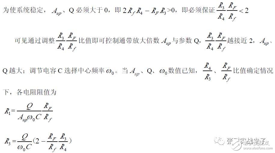
In order to stabilize the system, the coefficient of the first term in the denominator must be > 0, i.e., 3 - A_uf > 0, which means A_uf < 3.
(2) Amplitude-Frequency Characteristics
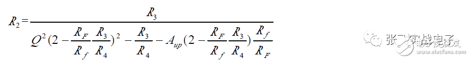
(3) Design Steps
In high-pass and band-pass filters, the op amp output does not need to be zero in static conditions, allowing for single-supply operation. In contrast, low-pass and band-stop filters often require dual-supply operation due to DC-to-AC amplifier requirements.
Band Stop FilterThe band-rejection filter (BEF) has exactly the opposite characteristics of the bandpass filter. It blocks signals between f_p1 and f_p2, mainly used to suppress signals in a specific frequency band.
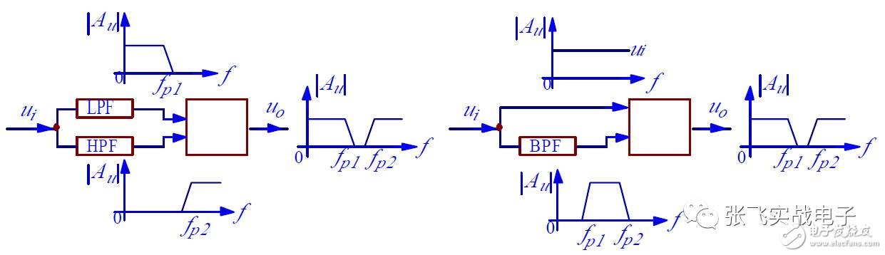
It can also be obtained by subtracting the BPF circuit output signal u₀ from the input signal u_i, as shown in (b). The BEF filter obtained through subtraction has the same characteristics as the BPF filter it is constructed from, meaning the central angular frequency ω₀ and the quality factor Q are the same as those of the BPF filter. Therefore, this type of BEF filter is easy to design, though it requires an additional op amp for signal subtraction.
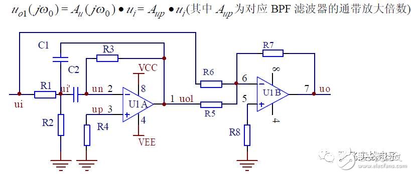
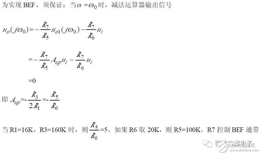
For example, a BEF circuit formed by a simple second-order inverting input BPF filter through subtraction is shown in the figure. According to the BPF filter's characteristics, when ω = ω₀, the BPF filter output signal

When generating a BEF through subtraction, a simple second-order BPF is generally used instead of a high-Q BPF because the latter requires more matching parameters and is harder to debug.
The BEF utility circuit using summation operations mostly employs a double T-type network active filter, as shown in the figure.
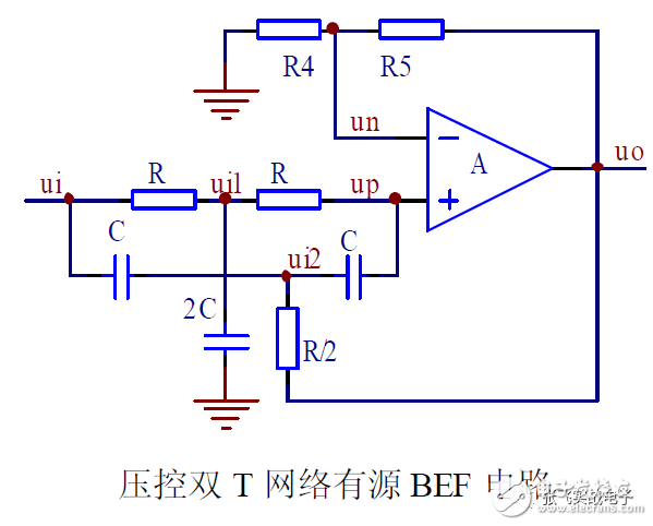
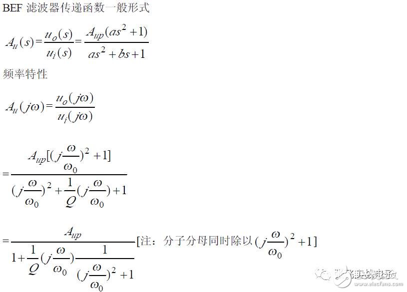
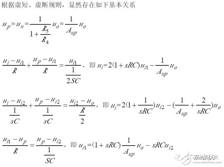
(1) Transfer Function
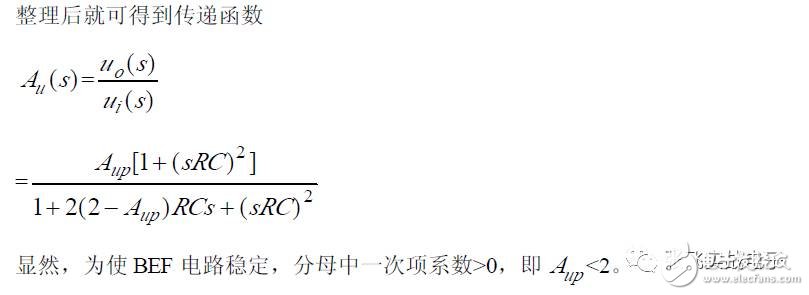
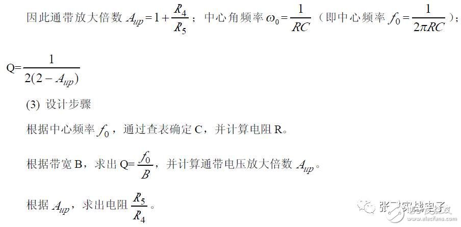
(2) Frequency Characteristics
The state variable filter has two types: inverting input and non-inverting input.
1. Inverting Input State Variable Filter
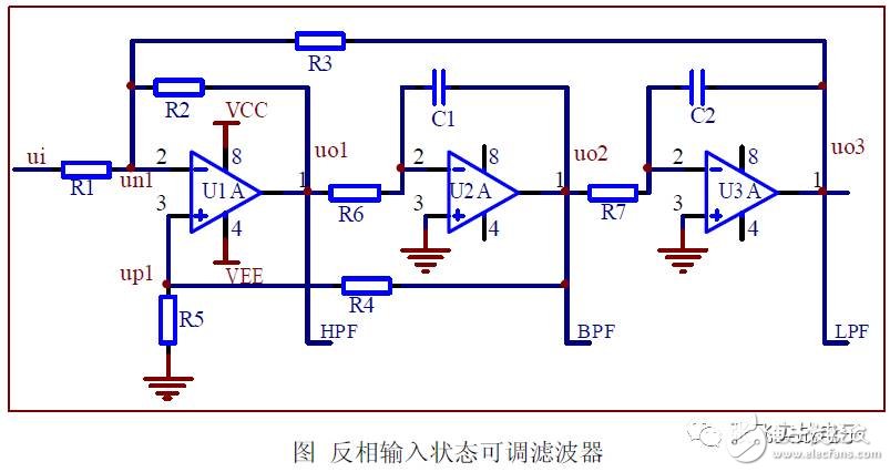
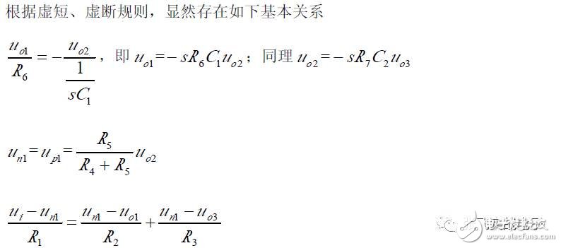
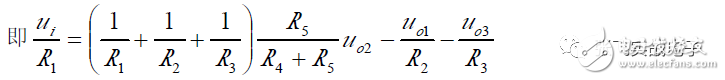
(1) Basic Relationship
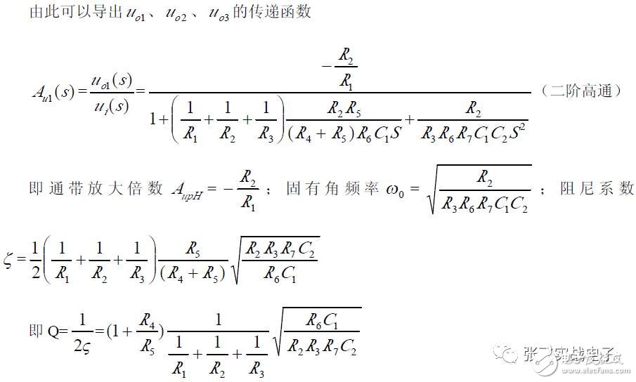
(2) Transfer Function
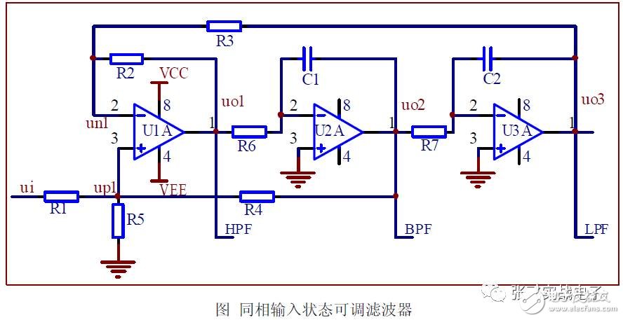
2. Non-Inverting Input State Variable Filter
(1) Basic Relationship
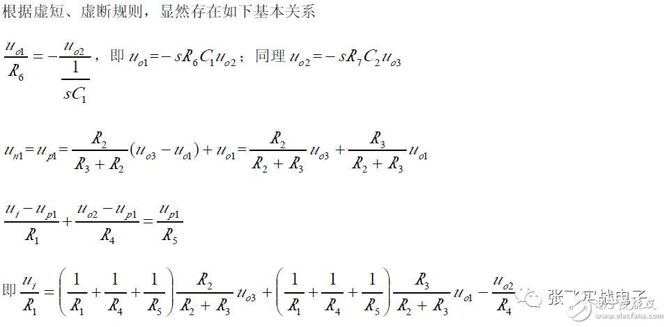
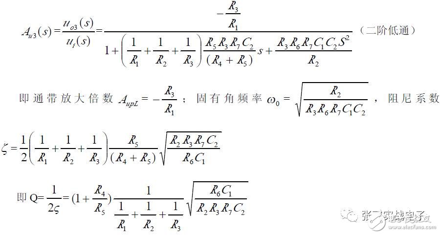
(2) Transfer Function
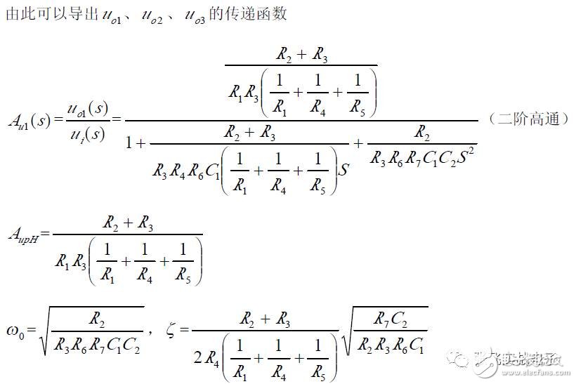
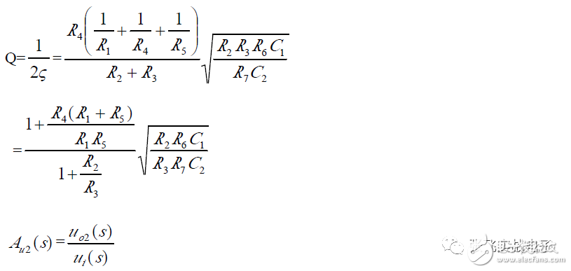
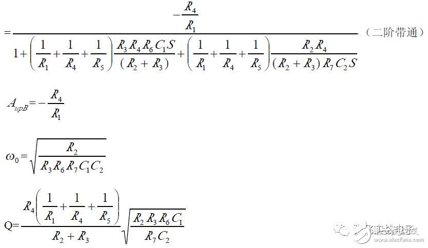
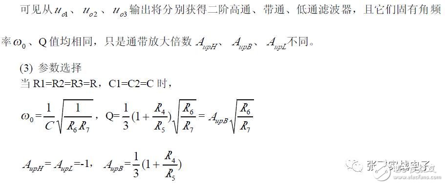
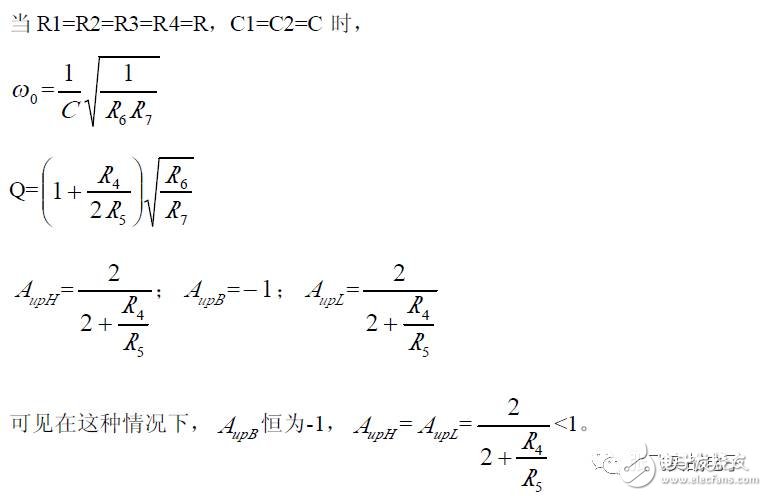
It can be seen that the non-inverting input state variable filters u_o1, u_o2, and u_o3 are outputs of the second-order high-pass, band-pass, and low-pass filters, respectively, with the same natural frequencies ω₀ and Q, but different passband gains A_upH, A_upB, and A_upL.
(3) Parameter Selection
Band-Stop Filter Formed by 3-State Tunable Filter
By combining the low-pass filter and the high-pass filter characteristics, the band stop filter can be formed. As long as the state of the tunable filter and the high-pass filtered output of the low-pass filtered output are fed into the summing amplifier (or non-inverting and inverting), the band stop filter is obtained, as shown.
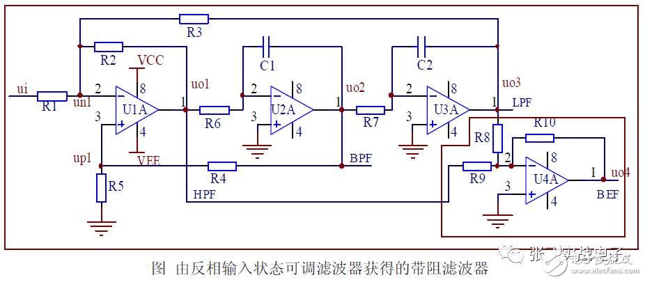
Since the passbands of the low-pass and high-pass filters in the state tunable filter are the same, R8 = R9 is taken in the BEF filter.
These filters are integrated and come in many varieties. Some can also be programmed by controlling internal electronic switches and selecting different capacitors.
All Accessories Of Laser Level
Green Laser Protective Glasses,Laser Protection Glasses,Laser Protection Eyewear,Laser protection
Guangdong Tumtec Communication Technology Co., Ltd , https://www.gdtumtec.com