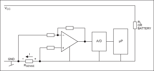
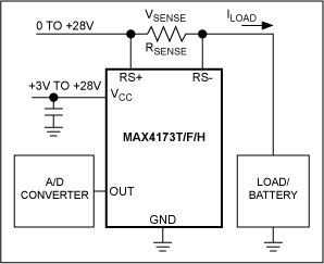
Current measurement (that is, detecting the current flowing into and out of an electronic circuit) is a must-have skill for the designer and is essential in a variety of applications. Examples of applications include overcurrent protection, 4–20 mA systems, battery chargers, high-brightness LED control, GSM base station power, H-bridge motor control, and you must know the current ratio (ie, charge) to and from the rechargeable battery in such applications. Meter function). With more and more portable applications, the demand for dedicated current monitors has increased dramatically to achieve their mission in a small package with low quiescent current. The following discussion covers low-side and high-side current monitors, including their architecture and applications. Is the high side or low side monitor used?Most current measurement applications use a low-side principle with a sense resistor in series with the ground path (Figure 1) or a high-side principle with a sense resistor in series with the power line (Figure 2). Both methods have different advantages and disadvantages. Low-side resistors add unwanted extra impedance to the ground path; circuits with high-side resistors must withstand relatively large common-mode signals. In addition, if the GND pin of the op amp in Figure 1 is referenced to the positive terminal of RSENSE, its common-mode input range must be covered below zero, which is GND - (RSENSE &TImes; ILOAD).
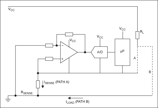
However, do not ignore the advantages of the high-side measurement method because of the simplicity of the low-side measurement circuit. Multiple faults bypass the low-side monitor, putting the load in a dangerous and undetected situation (Figure 3). Note that the load connected through path A can be detected, but the accidental connection through path B avoids the monitor. On the other hand, the high-side monitor is directly connected to the power supply and is capable of detecting all downstream faults and triggering corresponding remedies. High-side monitors are also suitable for automotive applications where the enclosure is used as a ground potential.
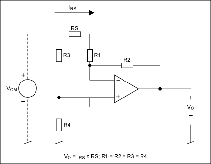
Previously, many implementations of both solutions were based on discrete components or semi-discrete circuits. In the simplest case, such high-side monitors require high-precision op amps and a few precision resistors. A common method of high-side measurement is to use a conventional differential amplifier as a gain amplifier and a level-to-earth level converter from the high side (Figure 4). Although this discrete circuit is widely used, it has three main drawbacks: The input resistance (equal to R1) is relatively low. The input impedance at the input typically exhibits large deviations. The resistors must be well matched to achieve an acceptable common mode rejection ratio (CMRR): a 0.01% deviation in resistance will reduce CMRR to 86dB, a 0.1% deviation will reduce it to 66dB, and a 1% deviation will reduce it to 46dB. .High-side current monitoring requirements have led to the development of a number of new integrated circuits for this purpose. On the other hand, low-side measurements have not advanced the progress of new related ICs.
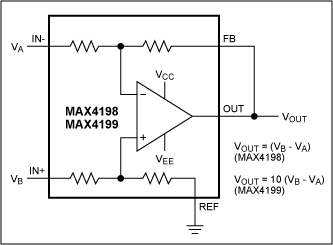
With the introduction of a large number of ICs including precision amplifiers and precision matching resistors, it is very convenient to use differential amplifiers in high-side current measurements. The CMRR of these devices is on the order of 105dB, and the MAX4198/MAX4199 are examples (Figure 5). The IC is available in an 8-pin μMAX package with a typical CMRR of 110dB and a gain error of better than 0.01%.
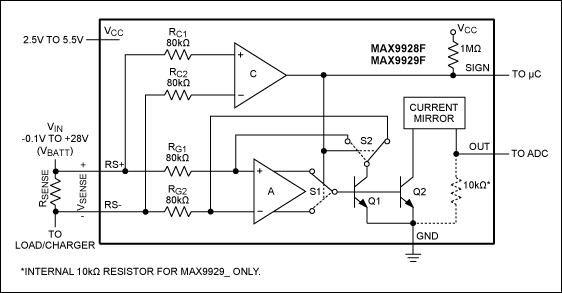
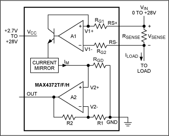
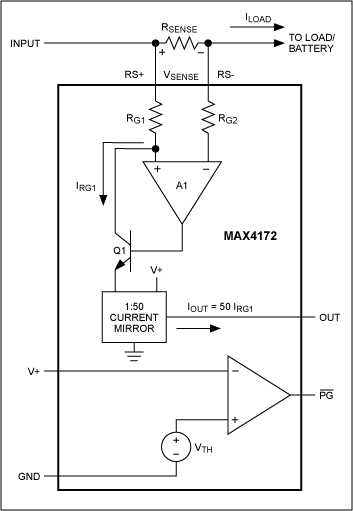
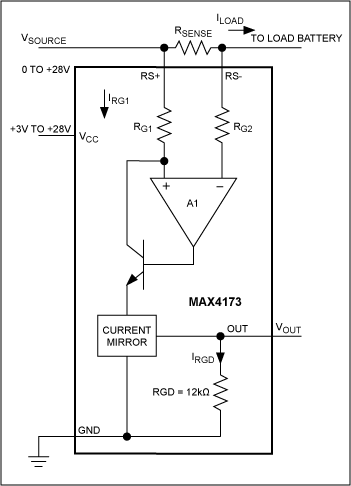
Another method of high-side current measurement is represented by an IC that contains all the functions required to perform the measurement. These ICs sense high-side currents at common-mode voltages up to 32V and provide a ground-referenced current or voltage output that is proportional to the current being measured. Power management, battery charging, and other applications that must measure or control current with high accuracy benefit from these dedicated current sense amplifiers. Maxim's high-side circuit sense amplifier places a current-sense resistor between the positive side of the power supply and the power input of the circuit being monitored. This design avoids external resistors on the ground plane, greatly simplifies layout and generally improves overall circuit performance. Unidirectional and bidirectional current sense ICs from Maxim include bidirectional devices with or without internal sense resistors. The bidirectional amplifier includes a signal pin for indicating the direction of the current. Models for these unidirectional and bidirectional current sense ICs include fixed gain, +20V/V, +50V/V or +100V/V fixed internal gain, and internal gain plus single or dual comparators. The device is packaged in a small package to meet the stringent requirements of compact applications. Common to all Maxim high-side ICs is the ability to provide a ground-referenced voltage or current output with little or no additional components. The output signal is proportional to the high-side current being measured and has a common-mode voltage of up to 32V. Figures 6 through 9 show several architectures for an integrated high-side current monitor. Note that the MAX4172 current source output is proportional to the voltage on RSENSE. The equation for the new high-side monitor shows that the effect of external resistors on CMRR is no longer an issue, as the current MRR (typically greater than 90 dB) is primarily dependent on the integrated amplifier. Integrating current sensing in a single IC has the following advantages: Strict tolerance for active and passive integrated devices Excellent temperature coefficient (TC) Small size Low power consumption Ease of use
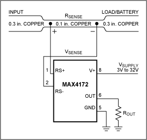
When designing any type of current monitor, it is important and important to carefully select the current-sense resistor (RSENSE). RSENSE should be selected according to the following criteria: Voltage Loss: A high RSENSE value causes the supply voltage to decrease through IR losses. The lowest RSENSE value enables the lowest voltage loss. Accuracy: A high RSENSE value can measure low current with higher accuracy because its voltage offset and input bias current offset are much smaller than the sense voltage. Efficiency and power consumption: At high currents, the I2R loss in RSENSE is large, so it should be considered when selecting the resistor value and power rating (watt). Excessively high temperature of the sense resistor also causes its resistance value to drift. Inductance: If the high frequency component of ISENSE is large, RSENSE must have low inductance. Wire wound chip resistors have the highest inductance and metal film resistors are slightly better, but low inductance metal film resistors (available below 1.5Ω) are recommended. Unlike metal foil and wound chip resistors (that is, spiral wound on the core), low inductance metal film resistors consist of straight metal strips. Cost: For RSENSE cost-critical applications, PCB traces can be used as sense resistors (Figure 10). Since the accuracy of the copper resistor is not high, it is necessary to adjust the full-scale current with a potentiometer. For systems with a wide temperature range, the copper resistance temperature coefficient is quite high (approximately 0.4%/°C).
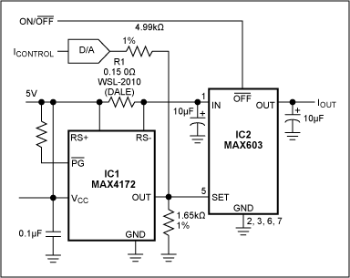
The circuit shown in Figure 11 is a variable linear current source. IC1 converts the R1 current to a proportional output voltage, causing the voltage regulator (IC2) to produce a regulated output current. To set IOUT to a regulated current between 0mA and 500mA, apply 5V to 0V on ICONTROL (5V sets IOUT = 0mA, 0V sets IOUT = 500mA). As an alternative, you can add a digital control of IOUT by adding a D/A converter as shown. For 12-bit resolution (60μA/LSB), the DAC can be a parallel input MAX530 or a serial input MAX531; for 10-bit resolution (250μA/LSB), the DAC can be a parallel input MAX503 or a series-connected MAX504.
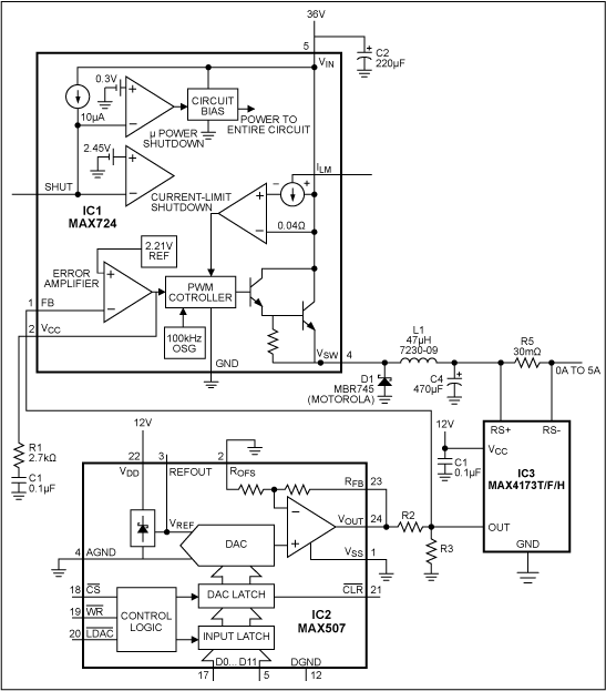
The circuit shown in Figure 12 is a 0–5A programmable current source that uses a 4V to 28V supply to generate 0A to 5A current. It has two advantages: a 12-bit D/A converter that enables digital programming; and a switch mode buck regulation. The device (IC1) makes it more efficient than an alternative current source using a linear transistor. Applications include overcurrent protection, 4–20mA systems, battery chargers, high-brightness LED control, GSM base station power, and H-bridge motor control.
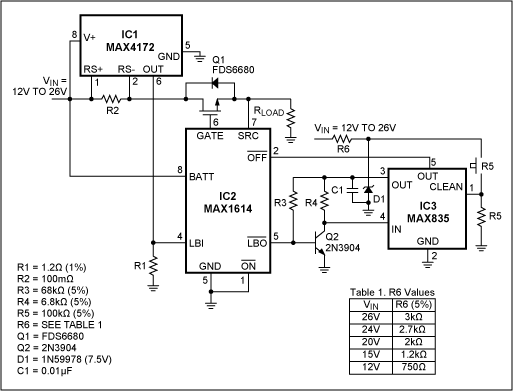
The widespread use of Universal Serial Bus (USB) has led to the development of various 2.7V to 5.5V overcurrent protection circuits, but there are few products above this voltage range. The shunt shown in Figure 13 operates at a 26V supply voltage and is triggered with a programmable current threshold.
|
Terminal Blocks Connector ,Electric Terminal Blocks Connector,Plastic Terminal Block,F Type Terminal Block Connector
Wonke Electric CO.,Ltd. , https://www.wkdq-electric.com

