introduction
This article refers to the address: http://
With the pollution of the environment and the energy shortage, electric bicycles have become more and more popular among people with the advantages of no waste gas pollution, no noise, convenient use of electric energy and ease of use, and become a means of transportation in life. This paper introduces a brushless DC motor speed control system designed by the high-speed SoC C8051F313 single-chip microcomputer of American company Silicon Laboratories (Silabs). The system makes full use of the on-chip resources of the C8051F313. The design scheme is simple in circuit, requires fewer peripheral components, and has low overall cost and good performance.
C8051F313
C8051F313 belongs to Silabs' high-speed SOC type MCU C8051F series. C8051F series MCU has high integration and is fully compatible with the traditional 8051 MCU core and instruction system, but its performance in all aspects far exceeds the traditional 8051 MCU. Because the "pipeline" structure is used to process instructions, 70% of the instructions have an execution time of 1 or 2 system clocks, which breaks the weakness of the traditional 8051 microcontroller's low operating efficiency, especially when it executes multiplication instructions as long as 4 system clocks. The execution of the divide instruction is as long as 8 system clocks. In addition, the C8051F series of microcontrollers integrates a wealth of peripherals, greatly reducing the need for peripheral components: analog multiplexer, programmable gain amplifier, ADC, DAC, voltage comparator, voltage reference, temperature sensor, SMBus ( I2C), Enhanced UART, SPI, Programmable Count/Timer Array (PCA), Power Monitor, Watchdog Timer (WDT), Clock Oscillator, etc. There are also on-chip FLASH program memory, RAM and XRAM. In programming languages, assembly and C programming are supported.
System hardware design
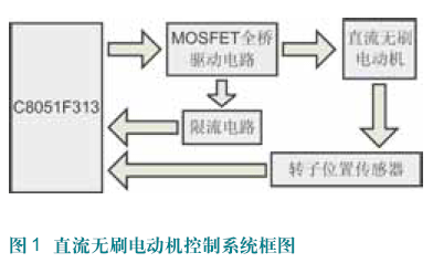
The whole control system mainly includes rotor position detecting circuit, speed measuring circuit, speed regulating circuit, MOSFET full bridge driving circuit, current limiting circuit, etc. Figure 1 is a block diagram of the control system. The DC power supply supplies power to the stator winding of the motor through the MOSFET circuit; the rotor position detecting circuit detects the position of the rotor, and controls the conduction and the off of the MOSFET according to the position signal of the rotor, thereby realizing electronic commutation; the speed measuring circuit detects the rotational speed of the motor, and the speed is adjusted. The circuit dynamically adjusts the motor speed (speed regulation) according to the detection result of the speed measuring circuit. This design can be designed to 60o or 120o electrical angle commutation as needed.

Rotor position detecting circuit and speed measuring circuit
The brushless DC motor in this design is a three-phase brushless DC motor, and the three Hall position sensors have a space spacing of 120o. The outputs H1, H2, and H3 of the three Hall sensors are directly connected to the three capture/compare modules of the C8051F313 PCA (Programmable Counter/Timer Array): CEX0, CEX1, and CEX2. The capture/compare module captures the rising and falling edges of the Hall signal and generates an interrupt. This method of detecting the rotor position of a brushless motor is superior to the method of using A/D conversion or using a comparator. The peripheral circuit is simple, almost does not require any peripheral components, and the real-time performance is very high, and the Hall signal can be captured reliably and quickly. A timer is also used to time the interrupt interval. This time reflects the speed of the motor. The software can process the speed of the motor at this time by a certain algorithm. The motor speed obtained by this method truly reflects the actual speed of the motor.
MOSFET full bridge drive circuit
This part of the circuit actually completes the function of motor commutation drive and speed regulation. C8051F313 performs real-time commutation drive on the brushless DC motor according to the detection result of the rotor position detection circuit, and adjusts the speed of the brushless DC motor according to the rotation speed detected by the rotation speed detection circuit. This design uses PWM to control the armature voltage to achieve speed regulation.

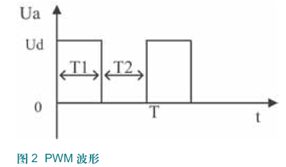
Ua in Figure 2 is the voltage across the armature of the brushless DC motor. The period of the PWM is T (a fixed value). Changing the duty cycle of the PWM, that is, changing the time of T1, then the ends of the armature of the brushless DC motor When the average voltage changes, the speed of the motor changes, and the purpose of speed regulation is achieved. The formula for Ua is:
Ua = (T1/(T1 + T2)) × Ud
This is the calculation formula of the PWM speed regulation of the armature voltage of the DC brushless motor. By energizing the brushless DC motor in the reverse order, the reversal of the DC brushless motor can be used.
In this design, a capture/compare module CEX3 of the PCA (programmable counter/timer array) of the C8051F313 is used to generate the PWM, and according to the actual needs of the commutation and speed regulation, the 1 is dynamically switched by the Crossbar (digital crossbar switch). The PWM wave is time-divisionally sent to the three lower tubes of the MOSFET full bridge for speed regulation.
software design
Because the C8051F313 is compatible with the traditional 8051 MCU, the assembly instructions are the same as the traditional 8051 MCU instructions. At the same time, it supports the most widely used Keil C simulation software in China. As long as you have 51 MCU programming experience or people who have used Keil C, it can be very easy. Get started with the programming of the C8051F313 without having to invest a lot of time in advance to learn.
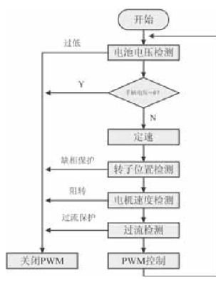
This design uses C language programming, and the program is highly portable. The program flow chart is shown in Figure 3.

Conclusion
This design makes full use of the resources on the C8051F313 chip, especially the resources of PCA. The three capture/compare modules of PCA subtly realize the detection of the rotor position of the DC brushless motor; one capture/compare module generates one PWM wave and dynamically distributes it to the three lower tubes of the MOSFET bridge for speed regulation, and also realizes Accurate measurement of DC brushless motor speed. The whole system has strong real-time performance, high reliability and good performance. Because the C8051F series of microcontrollers integrates a wealth of peripherals on the chip, the need for peripheral components is greatly reduced, and the overall system cost is relatively low.
Many types of jacks are available in the keystone module format, limited mainly by their physical size, including:
8P8C (RJ-45) modular jacks (computer networking)
F connector (TV antenna/cable/satellite)
4-pin mini-DIN (S-Video jacks)
HDMI jacks (high-definition video and audio)
Optical fiber connectors
BNC connector
What's more,we can also supply you Blank Patch Panel, face plate and surface mount box to use together with our modular jacks.

Keystone Jack, Cat6 Keystone Jack, Cat5e Keystone Jack, Rj45 Keystone Jack, Australian Keystone Jack
NINGBO YULIANG TELECOM MUNICATIONS EQUIPMENT CO.,LTD. , https://www.yltelecom.com
