
introduction
In the LED display engineering application, there is a single display project, but more are multiple display projects. For a single display, the direct use of the manufacturer's configuration of the control software will meet the requirements; but for multiple displays, especially system integration projects, the manufacturer's configuration of the control software will be difficult to meet the requirements. This is because, first of all, the control software configured by the manufacturer generally only implements common functions, and it is difficult to meet the requirements for personalized functions. For example, the integration project needs to be connected with the back-end database to realize real-time information release, and it is difficult for general control software to provide this. Item function; Secondly, for the integration project, the display information release is only one of the components, which requires a unified control and interface style; again, in a large integration project, there may be multiple vendors winning the bid, or engineering implementation. Replace or add products from other manufacturers after many years, and the implementation technologies of different manufacturers may differ.
Therefore, in order to meet the application of LED display in engineering, manufacturers generally need to provide secondary development interface for system integrators to carry out secondary development and complete system integration. After market research, the secondary development interface of LED display is not uniform, there is no unified standard, some are too simple, it is difficult to meet engineering applications, and some are too complicated, resulting in long system integration cycle and high cost. Therefore, after research, this paper proposes a new LED secondary development interface design method, allowing users to achieve system integration simply and quickly, while reducing the time and cost of secondary development.
1 main functional requirements analysis and model construction
In engineering applications, LED displays are mainly used to publish information, especially in real-time based on changes in the back-end database.
Typical applications are train stations, real-time updates of train times, soft/hard seat tickets, berth tickets, departure time and other ticketing information, as well as arrival and departure times, late trains and other arrival information, in addition to temporary notices, train changes, advertisements , waiting room location, etc.
In the integrated information management system of the railway station, the LED display information is only a part of the whole system, but the LED display type, communication type and distribution position may be complicated, as shown in Figure 1. According to the size of the display, the location of the display, the content and function of the display, the display can be divided into a total guide information screen, a waiting information screen, a partition screen, a ticket checking screen, a channel display screen, a station screen and an exit port information screen. Wait. In terms of communication, serial ports, networks, etc. are generally used depending on hardware conditions, location, and the like. The serial port is further divided into RS485 and RS232, one RS485 is connected to multiple displays, one RS232 is connected to one display; the network is divided into wired network, wireless network and GPRS.
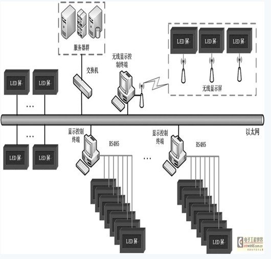
Figure 1 LED display typical system integration diagram
After comprehensive analysis, the functions of the system involving the display screen are:
(1) release information, update information, advertisements and guiding information; (2) control display screen, such as restart, time switch screen, setting parameters, etc.; (3) monitor display screen, display connection status, update time, and so on.
Its working process is:
(1) connect the display; (2) release information, download the program to the display; (3) control and monitor the display; (4) disconnect after the end of the operation.
In fact, the system call display function is not complicated, the main difficulty is:
(1) How to achieve a variety of hardware connection methods, including serial port, network; (2) how to organize a variety of information display objects, including text, pictures, animation, clock, etc.; (3) according to the control requirements of LED display, Provide basic control commands to adapt to a variety of system integration methods, including C / S, B / S and distributed, hierarchical control.
In order to solve these difficulties and achieve the purpose of versatility, simplicity and easy integration, after research, the model of the LED secondary development interface constructed in this paper is shown in Figure 2. The main functions and processes are as follows:
(1) Call the communication control interface, create its communication channel according to different communication methods, complete the LED display connection; (2) call the program production interface, create the program, add the program object, generate the program data, and then send the program using the command interface. To the display screen, complete the information release; (3) call the command interface, perform display restart, open/close screen, set brightness, update time, read display time, etc., complete the control and monitoring of the display; When exiting the system, close the communication channel, release the resources, and end the call operation of the secondary development interface.
2 key features of design and implementation
2.1 communication protocol design
The primary task of the LED display secondary development interface design is to define the communication protocol between the control terminal and the LED display. In order to achieve simplicity and transparency to the user, all communication methods here use the same protocol, and each command appears in pairs, corresponding commands and return commands, as shown in Table 1 and Table 2.
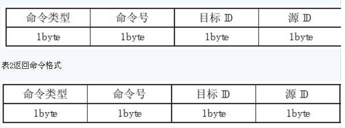
Description of each parameter:
(1) Command type: label command type ID, such as communication handshake command, file transfer and other control instructions;
(2) Command number: If there are multiple commands of a certain type, different command numbers indicate different commands of the type;
(3) Target ID: refers to the display ID, the default value is 0x01;
(4) Source ID: refers to the control terminal ID, the default is 0x00;
(5) Length: refers to the actual data length of the specific command;
(6) Data: data of specific commands or return results;
(7) Checksum: All checksum data of the protocol data except the checksum is generally calculated using arithmetic sum.
The command transmission logic is as follows:
(1) The sender sends a communication handshake command before sending a specific command:
Control source----------Send communication handshake command----------" Display control source "---------- return communication handshake command-- --------Display
If the control source receives the correct result, it indicates that the display is ready to receive data and can start sending specific commands. If you do not receive any return from the display, you need to check whether the physical link is normal, and whether the baud rate setting of the serial port is normal.
(2) The sender packs the specific command data into the display screen according to the previous format, and the display screen checks the data after receiving the data packet. If the verification fails, a request is resent.
(3) After the sender's command is successfully sent to the display, the display feeds back the result of the control card execution to the sender in the protocol packet format. If the verification fails, the display screen is re-issued to execute the result data; otherwise, the end result is sent to the display screen to end the command process.
(4) If the instruction in (2) is a file transfer instruction, repeat (2), (3) until the end of the file transfer.
During the communication process, the sender must force the end of the transmission process, and may send a communication handshake command or force abort communication for forced termination.
2.2 communication channel interface
Before the LED display is communicated, the communication channel must be established, and when the system is exited, the communication channel resources are released. Communication channel interfaces include:
(1) Open the communication channel
Function format: DWORDCOMM_Open (constPDeviceParampDevParam, DWORDdwNotify, DWORDdwWindws, DWORDdwMsg);
Parameter Description:
1pDevParam: indicates the parameters of the specified device, such as the baud rate of the serial port, the serial port number, and the parameters such as the local IP address and port number of the network. 2dwNotify: indicates whether to notify when the LED display has a return value, 0 means no notification, 1 means Notification; 3dwWindws: the form handle indicating the message notification; 4dwMsg: the user-defined message number.
return value:
10: indicates that the creation failed; 2 other values: indicates the device channel value.
Function description:
This function is used to establish a communication channel. Once the function is run, a channel is created. Upon successful establishment, a DWORD value is returned, representing a device handle, which is used to distinguish different channels. This value is used by other interface functions to control different display screens.
Physically support the serial channel, network channel, for the serial port, set the serial port number, baud rate, receive / send buffer, and then open the serial port; for the network, set the local IP, port number, receive / send buffer, and then open the network port . The special emphasis here is that the network uses UDP, which is mainly for:
1 Uniform with the serial port in the protocol implementation; 2 only need to be created once; 3 improve the network communication handshake connection.
For the sake of space, the following function will only list the function format and function description.
(2) Close the communication channel
Function format: DWORDCOMM_Close (DWORDdwDev/* communication device channel */);
This function closes the open communication channel (dwDev) and releases the communication channel resources, which are generally used before exiting the system.
(3) Forced suspension of communication
Function format: DWORDCOMM_Break(DWORDdwDev);
This function aborts the communication of the current communication channel (dwDev).
(4) Communication handshake
Function format: DWORDCOMM_Link (DWORDdwDev/* communication device channel */,
BYtebyDstNo/* target display ID*/,
Char*chHost/* network address, invalid at serial port*/,
WORDwPort/* network port number, invalid when serial port */);
This function queries the display for communication and can be used before communication or when monitoring the LED display.
2.3 program interface
The information displayed on the LED display is actually a program file, which is usually generated in the host computer control system and then sent to the display. When designing the program interface, there may be some differences in the details of the program structure. This paper designs a program interface according to the tree program structure shown in FIG.