
1 Introduction
The control area network CAN belongs to the field bus range. It is a serial data communication protocol developed by Bosch in Germany in the early 1980s to solve the data exchange between many control and test instruments in modern automobiles. It is a kind of The main bus, the communication medium can be twisted pair, coaxial cable or optical fiber, and the communication speed can reach 1 M bit/s. The biggest feature of the CAN protocol is to abolish the traditional station address coding and encode the communication data block. The advantage of this method is that the number of nodes in the network is theoretically unrestricted. The identification code of the data block can be composed of 11-bit or 29-bit binary numbers, so 211 or 229 different data blocks can be defined. By means of block coding, different nodes can also receive the same data at the same time, which is very useful in distributed control systems.
2 system design
In many places where the field or measurement environment is poor, a data processing transmission system that is small in size, high in data processing performance, and stable in remote transmission is required. Aiming at this requirement, a multi-node remote data acquisition and transmission system was designed. The data collection of each node to be detected at the remote end is sent to the DSP for processing, and the data of each node is transmitted to the CAN bus through the CAN control interface of the DSP, and then the data exchange and control are performed with the serial communication port of the DSP and the host computer. operating.
The system uses DSP as the microprocessor, making full use of the advantages of small size, low power consumption and powerful data processing functions of the DSP device. At the same time, the CAN bus is used to transmit data, which is not only simple in structure (only 2 lines are connected to the outside), and the transmission is performed. The stability is high and the transmission distance is long. In particular, the communication data blocks of each node in the network can be independently coded, the flexibility of data reception is increased, and the number of network nodes is expanded. At the same time of data acquisition and processing, the system can easily communicate with the local PC using the SCI serial port of the DSP. The scheme design based on the above advantages solves the problem of data processing transmission in many cases where the working environment is bad and the detection points are large.
The DSP24xx family from Texas Instruments is a low-cost, high-performance 16-bit fixed-point DSP chip from TI that is designed for digital motor control and other control applications. The TMS320LF2407 chip was selected as the data processing chip to transmit data with the host PC. TMS320LF2407 comes with CAN controller (conforms to CAN bus 210 protocol), and can realize the self-receiving function of CAN controller by setting the self-test bit of internal register, which is convenient for debugging the lower-level machine of CAN communication. Based on this functional module of the chip, the hardware design can communicate with other CAN nodes as long as it is connected to the CAN bus through the CAN driver (level shifting). The communication part between the DSP and the host computer can be realized through the SCI asynchronous serial communication port. The system structure diagram is shown in Figure 1.
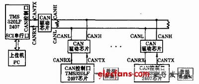
Figure 1 system structure diagram
3 hardware design
The DSP chip used has its own CAN controller module and SCI serial communication port, but there is a problem of level-driven conversion in the connection of each node of the system and communication with the PC.
The CAN driver chip uses TI's UC5350 driver chip. Designed for industrial applications using CAN communications, the UC5350 controller area network converter features high-speed transceivers up to 1 Mbit/s and can connect to at least 110 nodes. Figure 2 shows the hardware connection of the UC5350 and TMSLF2407 chips.
It should be noted that on the two terminal CAN nodes of the CAN transmission network, a 120 Ω resistor R2 must be connected between the CANH and CANL signal lines of the node, in order to eliminate the backflow interference during transmission. .
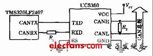
Figure 2 CAN driver hardware diagram
The communication part between the DSP and the host computer is implemented by the SCI asynchronous serial port of the TMS320LF2407. Since the serial port input and output of the TMS320LF2407 are both TTL level, and the serial port of the IBM-PC is designed according to the RS-232-C standard, level conversion is required to achieve communication between the two. In the design, the driver chip MAX232 that conforms to the RS-232 standard is used for conversion between levels. Figure 3 shows the hardware diagram of the interface between the DSP and the PC serial port.
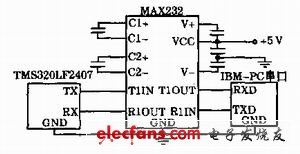
Figure 3 RS232 serial port driver hardware diagram
4 software design
4. 1 Design of communication program between CAN modules
The CAN module of the TMS320LF2407 is a 16-bit peripheral that supports the CAN2.0B protocol. The CAN module has 6 mailboxes (MBOX0~MBOX5), of which 2 receive mailboxes (MBOX0, MBOX1), 2 send mailboxes (MBOX4, MBOX5) and 2 can be configured to receive or send mailboxes (MBOX2, MBOX3); Local mask registers and 15 control/status registers for mailboxes 0, 1, 2, and 3. Access to it is divided into access to control/status registers and RAM access to mailboxes. These mailboxes are located in a 48 &TImes; 16-bit RAM that can be read or written by the CPU or CAN.
Since the system is a multi-node remote data transceiver system, it is very important to correctly initialize the CAN modules of each node. Initialization must set the communication baud rate and synchronization jump width of the CAN module in each node to be the same, and configure the receiving code and mask code in the node module. The mailbox ID and information control registers are then configured in the format of the transmitted data frame.
4. 1. 1 Initialization bit timer
The baud rate setting in CAN communication is related to the system control status register SCSR1, the timers BCR1 and BCR2 in the CAN module (where BCR1 and BCR2 determine the communication baud rate, synchronization jump width, sampling times and weight of the CAN controller). Synchronously) . When initializing the registration timer, be sure to set the change configuration request bit in the CAN module main control register MCR to 1, that is, CCR = 1, and determine whether the change configuration enable bit CCE in the global status register GSR is 1. If it is 1, the following initialization work can be performed. After completing the initialization of the registration timer, the CCR bit needs to be cleared to enter the normal operation mode. When configuring BCR1 and BCR2, set the CAN controller baud rate according to the following formula:
Baud rate = ICLK / [ ( BRP + 1) + BitTime ]
Where: ICLK is the clock frequency of the CAN controller, that is, the system frequency of the DSP fixed in SCSR1; BRP is the baud rate prescaler, which determines the time slice TQ of the CAN controller, TQ = ( BRP + 1 ) / ICLK; BitTime = ( TSEG1 + 1) + ( TESG2 + 1) + 1 , TSEG1 is time period 1 and can be programmed to 3 to 16 TQ time slices. TSEG2 is time period 2 and must be less than or equal to time period 1.
4. 1. 2 Initialize the mailbox
The initialization of the mailbox is to initialize the relevant registers in the mailbox, mainly used to set the identifier of the mailbox to receive or send the message, whether to send a remote frame or a data frame, and assign an initial value to the transmitted data area. The procedure is as follows: the mailbox is disabled, that is, the mailbox enable bit MEn (n = 0~5) in the direction of the mailbox/enable control register MDER is written with 0; the data field change request bit in the MCR register is set to 1; the content of the mailbox is configured. ; Return to normal mode; enable mailbox.
4. 1. 3 Receiving and sending mailbox information
After completing the above initialization work, you can transfer to the mailbox transceiver program. In order to continuously transfer a large amount of data on the system network, two data buffers (read and write 2 data areas) are set in the memory to store the data to be sent and received. When sending by mailbox, the data to be sent is written from the write data storage area to the data area of ​​the sending mailbox, and then the sending mailbox is enabled and the sending request bit in the TCR register is set to 1, and the sending response signal and the sending interrupt flag are judged. The transmit interrupt flag and transmit acknowledge bit are cleared after successful transmission.
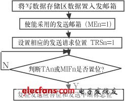
Figure 4 data transmission flow chart
Paraffin Wax Color 22g Sprial candles aslo called Novelty candles with shirink pack each peice in blue window box .very popur in Arab market .
evey year we can ship 40-50containers spiral candles to Sandi Arad ,the packing is 12pcs color candles in one box and 24box in one carton .color is yellow red green blue orange and white .the color is very pure .
welcome to visit my factory
shipment in the 30days after get the depsoit
Spiral Candle,Professional Spiral Candle,Spiral Taper Birthday Candle,Spiral Paraffin Wax Candles
Shijiazhuang Zhongya Candle Co,. Ltd. , https://www.zycandlefactory.com