
Car headlights are an important part of safe driving. Traditional headlamps have a blind spot of illumination when the car turns, affecting the driver's judgment of the obstacles in the curve, and there are other safety hazards. In order to improve safety, today's Adaptive Front-Light System (AFS) is becoming more and more widely used in smart car electronics. AFS uses a stepper motor to adjust the beam in real time, eliminating blind spots in the lighting, optimizing the visibility of the curve, and effectively increasing driving safety. ON Semiconductor has developed a series of driver chips for the stepper motor of the AFS system, which brings simplicity and convenience to the customer's design. This article focuses on AFS characteristics, stepper motor driver ICs and design points, and more specifically analyzes the difficulty of stepper motor driving, which helps the designer to develop an effective AFS solution quickly and accurately.
This article refers to the address: http://
AFS application effect and composition
The car AFS uses a stepper motor to adjust the left and right and horizontal height of the illumination beam, providing a safer lighting effect than conventional headlamps. If a traditional headlamp is used, the direction of the light and the body are always the same, and the blind area inside the curve cannot be effectively illuminated when the car turns. On the contrary, when the AFS car is turning, it can rotate according to the angle of the steering wheel, and the effective beam is projected onto the front road surface that the driver needs to see, which is more conducive to eliminating the blind spot of illumination. The right side of Figure 1 lists the actual lighting effects without AFS and AFS for left and right adjustments, which is clearly more effective for safe driving.
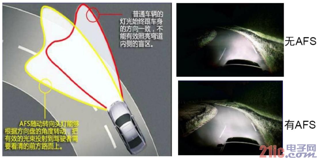
Figure 1: Comparison of illumination areas without AFS and AFS with left and right adjustment beams
Figure 2 shows the level adjustment effect of the AFS function. The picture above shows the effect of the light when the level is good. The middle picture shows the situation where the road bumps up when the car starts or goes uphill. The picture below shows the situation where the car is bumping when the car is braking or downhill. AFS can adjust the height of the middle and lower pictures in real time according to the tilt of the car body to achieve the effect of the above figure.
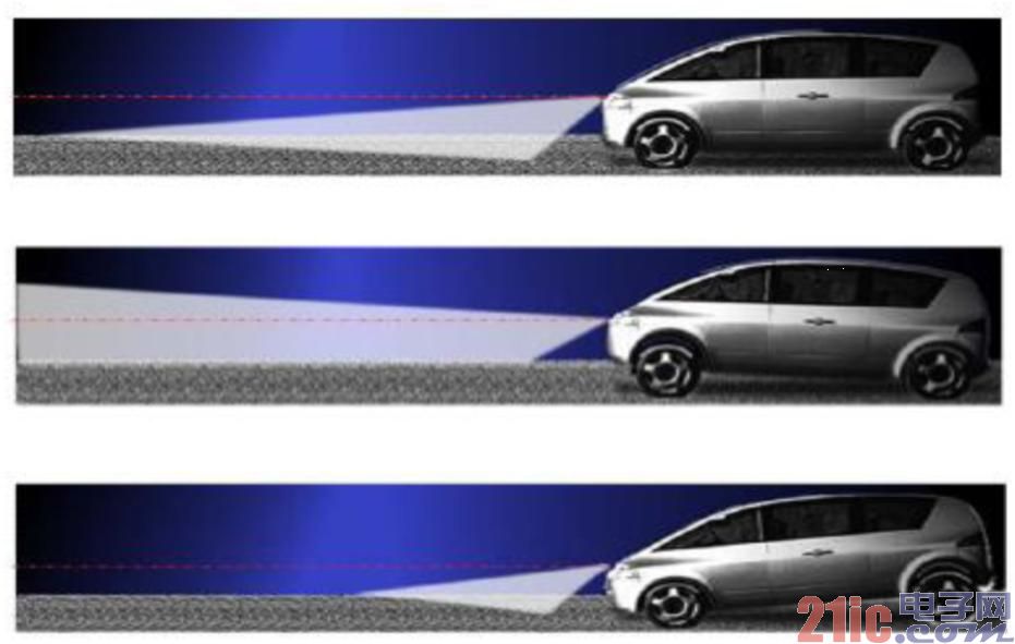
Figure 2: Level adjustment effect of the AFS function
An adjustment motor for level adjustment and a rotary motor for controlling the rotation of the light can be seen in the AFS control headlight structure diagram of FIG. The working principle of AFS control headlights is that AFS calculates the track angle by steering wheel rotation angle and body speed. The steering wheel rotation angle coefficient is the centripetal force of the curve, and the body is the tangent of the curve. The relationship between the two is the curve. The angle of the angle of investigation, calculate the curve angle to drive the rotary motor to the desired corner angle. Similarly, the front and rear axle sensors of the vehicle body can obtain the calculated value of the inclination of the vehicle body, and the height of the light is adjusted by the motor to correct the inclination of the vehicle body to adapt to the lighting requirements of different road gradients.
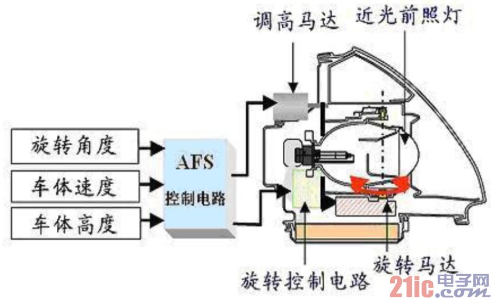
Figure 3: AFS control headlight structure
ON Semiconductor's different stepper motor driver solutions for AFS
To effectively drive a stepper motor in AFS, a suitable stepper motor driver solution must be used. ON Semiconductor offers a variety of stepper motor driver solutions for AFS, including AMIS-30621, AMIS-30623, NCV70521, and NCV70522. These stepper motor driver products each have their own focus. For example, AMIS-30621 and AMIS-30623 adopt LIN communication mode; NCV70521 and NCV70522 adopt SPI communication mode; AMIS-30623 has self-locking detection function; AMIS-30621, AMIS-30623 and NCV70522 have built-in 5V power output; NCV70522 built-in watchdog Reset signal.
From the application point of view, AFS stepper motor drive scheme is divided into two categories: direct drive and mechatronics product application. In contrast, the NCV70522 uses direct drive, and the stepper motor driver chip is required to be mounted on the same printed circuit board (PCB) as the microcontroller (MCU), and each motor needs a corresponding signal cable, suitable for medium and high. The integration execution plan is applied; while the AMIS-30623 is suitable for mechatronics applications, the stepper motor driver chip can be directly installed in the motor structure, and only needs to share the ground wire and LIN bus signal connection, which is suitable for high integration execution plan application. , as shown in Figure 4.
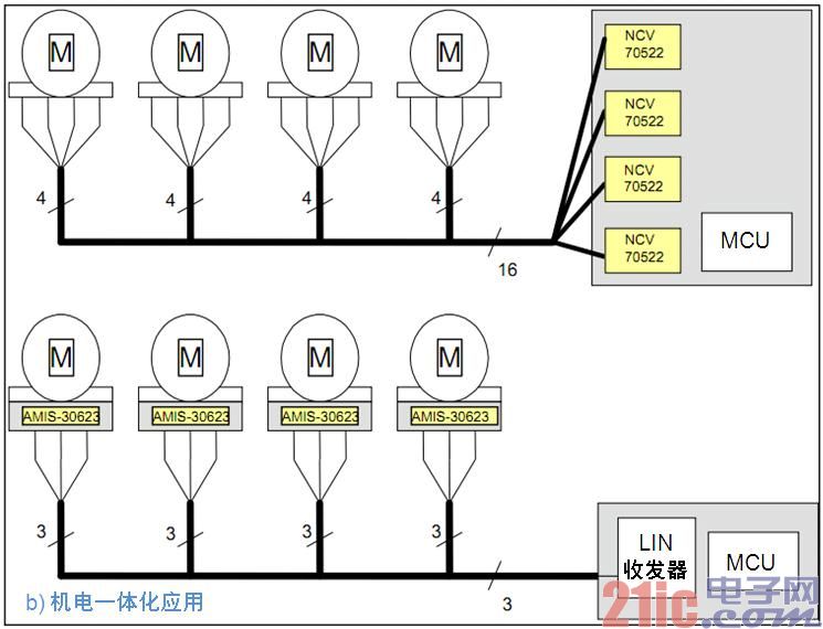
Figure 4: Comparison of direct drive and mechatronic product applications
The stepping driver chip AMIS-30623 with stall detection function is a single-chip micro-stepping motor driver and controller using LIN communication. It is a dedicated mechatronic solution for remotely connecting to the host via LIN. The chip receives positioning commands via the bus and then drives the motor coil to the desired position, configurable parameters such as current, speed, acceleration and deceleration. The chip has its own motor stall detection. Other features include: AMIS-30621-like features, improved low-voltage management, improved LIN loss, 0 mA holding current, AMIS-30621 compatibility, reduced noise (blocking detection), and reduced risk of over-temperature under maintenance conditions. The market and applications of the solution cover automotive headlight actuators, idle speed control, liquefied gas valves and suspension valves.
The NCV70522 is a SPI communication single-chip microstepping motor driver chip with a voltage regulator and a watchdog. It features output current selectivity, an SPI interface, an embedded 5 V regulator, and a watchdog reset. It is a simplified circuit designed for peripheral-driven microcontrollers. The chip can receive the pulse signal through an input pin to start the "next microstep" command, output coil current, microstep number, etc., and perform diagnostic feedback through the SPI bus setting. Its unique features include: equal to NCV70521 + 5 V regulator and watchdog reset, transparent SPI parameters, 2 signal control operation (NXT / DIR), microstep mode from 1 to 1 2 precision, flexible operating current Up to 1.6 A, ERRB pin output error status, the same advantages as NCV70521, compatible with NCV70521, reduced PCB board size and BOM cost (built-in voltage regulator), and improved application security (built-in watchdog). The program is suitable for automotive headlight actuators, idle speed control, liquefied gas valves, suspension valves, and folding multimedia displays.
AFS stepper motor drive difficulties and design points
Taking NCV70522 as an example, its control elements include stride mode, NXT and DIR. The stride mode includes 7 steps from 1st to 1/32; NXT is the next step, and the corresponding Ix and Iy are output according to the ammeter; DIR is the motor running direction control. As shown in Figure 5.
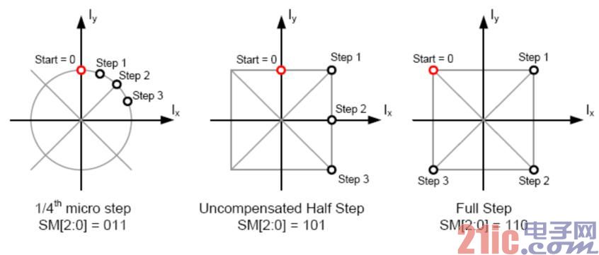
Figure 5: Control elements
The SLA (Speed ​​Load Analog) signal is a signal sampled and supplied by the SLA pin and can be applied to motor stall and resonance characteristics detection. Successful design requires an understanding of the characteristics of the Vbemf (back EMF) signal. The signal that Vbemf is phase-delayed with the motor coil winding current (ICOIL) is called the load angle. The magnitude of the back EMF varies with rotor speed and load angle and is affected by motor load conditions. Vbemf is visible when there is no current in the coil (= current zero crossing), as shown in Figure 6.
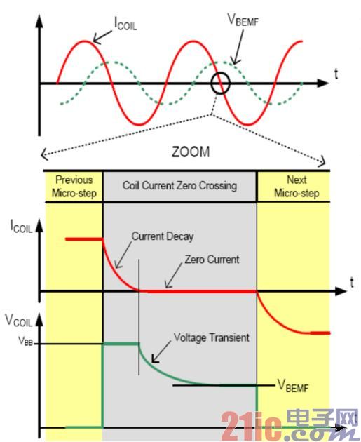
Figure 6: SLA signal characteristics
The SLA signal has a resonant feedback characteristic, which is generated by the mechanical structure of the motor and the resonance of the luminaire. In practice, it can be avoided by detecting the resonance point of the motor and the luminaire at different speeds.
Figure 7 shows the simplified driver circuit for the AFS NCV70522 solution. The NCV70522 has a built-in LDO power output that can be selected by the MCU. This solution uses SPI communication, so you need to pay attention to I/O port control, such as NXT signal, DIR signal and ERROR signal status reading. Since the SLA signal is an analog signal, it should be connected to the AD pin of the MCU; the series resistance and parallel capacitance of the SLA signal, and the resistance and capacitance of the LC filter circuit must be very accurate; in addition, the SLA signal is in the layout diagram. Be sure to use the most simplified and straightforward wiring.

Figure 7: AFS NCV70522 solution simplifies the drive circuit
When resetting the AFS NCV70522 chip, the CLR pin is 0, the chip is in normal mode; the reset chip needs to set the CLR pin to 1; after reset, the chip internal register value is cleared to the initialization value. When setting the output current, you can use the various output current modes provided by the chip to select by the SPI register CUR[4:0]; the changed current will be updated in the next PWM cycle. The chip offers a total of seven mode selections from full step to 32 microsteps. The stride mode setting can be selected via the SPI register SM[2:0] setting. The enable of motor operation can be achieved by setting the MOTEN bit in SPI. Use the NXT signal to control the motor step position, change the step position corresponding to the ammeter to output the corresponding Ix and Iy; even if the motor is not enabled, the step position can be changed, only Ix and Iy are not output; the register NXTP flag setting determines Acquisition of the rising or falling edge of the NXT.
The decision to stall is very complicated and important for the AFS system. In the AFS NCV70522 application stall determination method, the motor running speed (Fstep / s) = NXT frequency / micro-step number; each time the NXT pulse is generated, the step position is changed once, when the micro-step is more precise, the more NXT is needed The longer the period of the ammeter change. After the motor microstep mode is set, we can adjust the motor running speed by the frequency of the NXT. During stall detection, the SLA pin provides an output voltage that represents the voltage at the level of the back EMF motor. This back EMF voltage can be sampled at each zero crossing, and each coil current has two zero crossings, so there are four observable zero crossing current intervals in each electrical cycle. By reading the step position, you can get the zero-crossing information, and collect BEMF in the middle of the two zero-crossing points, which is more stable and accurate. SLA feedback differs depending on motor running speed and mechanical load, so each solution needs to compare the SLA between normal operation and stalled operation to determine the detection condition of the stall.
Typically, if two of the four "coil current overcurrent points" have SLA levels below 1.5 V, they are in a stalled state. In addition, more than two consecutive SLA waveform diagrams are needed to determine the stalling. The electrical cycle is determined to be a stalling of the electrical circuit, because the burrs of plastic parts of some luminaire structures can cause some friction and affect the stalling. judgment.
to sum up
The beam rotation of the automotive adaptive front lighting system helps to optimize the visibility curve and adjust the beam to real-time conditions. Stepper motors are the preferred controller for AFS. As a leading semiconductor solutions provider, ON Semiconductor has been using its advanced automotive process technology to provide a wide range of standard and custom devices for automotive lighting applications. Including the various AFS stepper motor driver solutions described above, ON Semiconductor's automotive applications meet automotive reliability and temperature specifications and environmental requirements, and meet people's interior lighting control, headlights, rear combination lights, Increasingly high requirements for fog lights, position lights, and especially new light sources allow drivers to fully experience the comfort and fun of driving.

Pay attention to ON Semiconductor's official WeChat to learn more innovative and energy-efficient solutions
The Drone Pllugs include XT90 Plug,AS150 Plug,AS150 Connectors,XT60,XT30,MR30,MT30,T60 and 3.5mm Banana Connectors ,4.0mm Banana Connectors.
Xt90 Connectors,Xt60 Connectors,Xt30 Plug,Xt60 Drone Connectors,XT90 Plug,AS150 Plug,AS150 Connectors
shenzhen GC Electronics Co.,Ltd. , https://www.jmrdrone.com