
1 Introduction
This article refers to the address: http://
With the rapid development of infrared imaging technology, infrared measurement television has become an important part of the photoelectric tracking system. The automatic and continuous focusing of the infrared camera is the key technology to ensure the quality of infrared TV imaging and realize high-precision and stable tracking of the photoelectric tracking system. In general, there are many factors affecting infrared TV imaging, and the parameters such as the distance of the target and the ambient temperature have a great influence on the imaging quality. How to adjust the position of the camera in real time according to the information of the target image quality such as the target distance and the ambient temperature. In order to obtain a clear target image, extensive and in-depth research is needed, which is of great significance for realizing the stable and high-precision tracking measurement function of the infrared tracking measurement system.
2. Focusing controller hardware design
2.1 Overall structure and principle
Photoelectric tracking measurement system The functions to be realized by the focus control system include: receiving the control commands of the integrated controller, realizing the zooming and focusing functions of the infrared TV, combining the self-checking function and fault diagnosis capability, and fault diagnosis to the circuit board.
The system uses a DSP+FPGA based dimming focus controller. The hardware block diagram of the controller is shown in Figure 1.
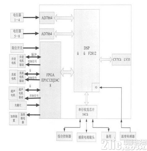
Figure 1 Dimming focus controller hardware block diagram
Among them DSP (TMS320F2812) as the core of the dimming focus controller. TMS320F2812 is TI's digital control field. It is the highest performance processor in the control field. It has the advantages of high control precision, fast speed, flexible use and high integration. It has been widely used in industrial automation, optical network and automation. Control and other fields.
The system uses EP1C12Q240C8 in Cyclone series FPGA as the timing and logic control core of the whole dimming focus controller. EP1C12Q240C8 provides 12060 logic units (LE) and 173 I/O ports, which can embed 4K RAM.
Apply part of all TMS320F2812 peripheral interfaces, such as GPIO interface and EVA/EVB interface.
With programmable logic devices (FPGAs), the hardware circuitry of the DSP can be designed very simply. The DSP data bus, address bus, read and write control lines, and interrupt signal lines are all introduced into the FPGA, and timing and logic design are completed in the FPGA according to specific requirements. Among them, TL16C554, AD7864 provides address strobe signal, providing quadruple frequency phase discrimination and counting logic for grating scale calculation.
Since the number of signal lines and limit switch lines of the motor is large, the number of I/O ports of the system needs to be large, and the function of expanding the I/O port can be completed in the FPGA.
2.2 FPGA design
The FPGA uses modular design ideas to decompose the FPGA design. It mainly includes the functions of implementing FPGA extended I/O port, providing chip selection and read/write signals for TL16C554 and AD7864, providing quadruple frequency phase discrimination and counting logic to calculate the position of the scale. The functional modules in the FPGA are shown in Figure 2.
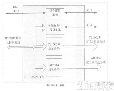
TL16C554 address decoding module: In the FPGA, the DSP reads and writes and decodes the address signal, and provides signals for reading and writing signals and chip selection for the TL16C554.
AD7864 address decoding module: decodes the address signal of DSP, and provides signals for reading, writing, chip selection and channel selection for AD7864.
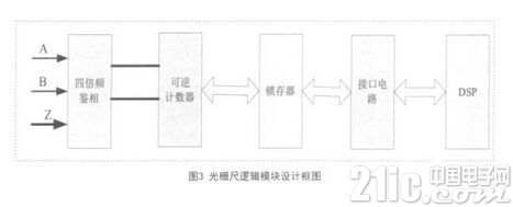
The grating rule logic calculation module: the grating scale outputs two orthogonal square wave signals A, B and zero bit signal Z input into the FPGA, realizes the frequency multiplication and phase discrimination function of the A and B signals in the FPGA, and then passes the 16 The bit counter and the latch are connected to the DSP, and the position value of the scale is obtained by reading the value of the counter. The system block diagram is shown in FIG.
3. Experimental verification and accuracy analysis
3.1 Experimental verification
The focusing system consists of an optomechanical part mounted on the telescopic objective barrel and an electronic control section. The optomechanical part includes a focusing component, a zooming component, and the like. The electronic control system uses DSP2833 as the core processor, and uses FPGA to realize timing and logic control, with peripheral circuit, execution motor and position feedback component. The position feedback of the electronic control system adopts a precision wirewound potentiometer and a grating ruler, and the execution motor adopts a stepping motor, an ultrasonic motor and a permanent magnet DC motor. Both ends of the zoom system rely on electrical limits and mechanical limits to ensure positioning.
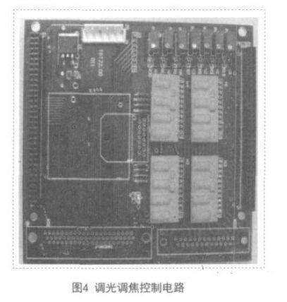
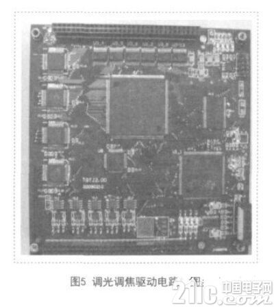
According to the above design scheme, the focus control electronic control system uses two circuit boards to work, which are control circuit board and power drive board. 4 is a control circuit board, and FIG. 5 is a power drive board. Through the test, the infrared TV automatic focusing and zooming function is better completed.
3.2 Accuracy analysis
3.2.1 Infrared TV focusing control
The infrared TV focusing range is 200m~∞, and the focusing execution motor uses Haydn linear motor model as 21000 series Size 8 linear stepping motor with a step size of 0.0015mm, its working voltage is 5V, and the current per phase is 0.24A. A thrust of 60 N can be generated at a speed of 1000 steps per second. Meet the requirements for use. The position feedback uses an incremental scale.
The error source of the focus control system is the step size of the linear stepper motor and the accuracy of the scale. The linear stepping motor has a step size of 0.0015mm. The following conditions are calculated and the following conclusions are drawn:
a) The linear stepping motor has a step size of 0.0015mm, the resolution of the focusing mechanism is 0.0015mm for the linear stepping motor; b) the grating measuring rod is used as the position measuring sensor, and the measuring precision is high, and the measuring precision is high. 5μm, meeting the resolution accuracy requirement of ±0.01mm; c) The speed of 1000 steps per second is the common speed of the motor, that is, the stroke per second is 1.5mm, so the speed meets the requirement of focusing time.
3.2.2 Infrared TV zoom control Infrared two-speed zoom motor uses Jiangsu Chunsheng's ultrasonic motor, model TRUM-60. Infrared zoom system is 100mm/300mm two-speed zoom, semi-automatic control mode, electronic control system The ultrasonic motor is controlled to switch the variator group to switch the focal length of the infrared television.
The self-locking characteristic of the ultrasonic motor's power-off ensures the stability of the rotary zoom mechanism. The self-locking torque of the ultrasonic motor is greater than about 30% of its driving torque. The rotating shaft of the ultrasonic motor is directly connected to the outer casing of the variator lens set. This structure is simple and reliable, and takes up little space.
Since the speed of the ultrasonic motor can reach 4~150r/min, for the zoom mechanism that only needs to rotate 90 degrees, if the switching time is less than 2s, then the speed n is satisfied:
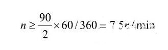
It can meet the requirements for use. Therefore, the ultrasonic motor used fully meets the technical requirements.
4 Conclusion
Photoelectric tracking measurement system Infrared TV focusing control is the key technology for the system to stabilize high-precision tracking target. The infrared TV focusing controller designed by DSP as the core processor and FPGA for timing and logic controller is tested and tested by practice. The accuracy analysis satisfies the technical index requirements of the photoelectric tracking system to adjust the focal length in real time according to the target distance, ambient temperature and other parameters.
Peel Mask PCB
Peel able masks are used in order to protect selected solder holes against plugging during mass soldering or to protect carbon elements and gold plated contacts during mass soldering. Peel able masks are screen printed.
Requirements
• The peelable mask must adhere sufficiently well to the PCB so that it does not peel off when handled correctly.
• It must be able to endure a two to three time soldering process without peeling off, but must remain detachable.
•After soldering of the PCB, the peelable mask must be able to be detached – preferably in one piece. In case of metallized holes, no mask
residue must be left in the drill holes or on the surface of the PCB. In the case of non-metallized drill holes, however a certain amount of residue
can remain.
• The peelable mask must be able to resist conventional solvents such as chlorinated and fluorinated hydrocarbons, isopropanol, conventional
fluxes and similar.
• Particular requirements: The roughness U of the edge of the mask can be 0,5 mm from the tip to the base (left figure
below).
Peel Mask Board,Green Peel Mask Board,Quick Turn Peel Mask Board,Mask Board
Storm Circuit Technology Ltd , https://www.stormpcb.com