In this section, we will first understand the clock resources of the protagonist XC6SLX16 (Spartan-6 family) on Nexys3. Of course, we will not copy the contents of ug382.pdf (I suggest you go through it), but as a rookie. "The privileged classmates can only talk about it with water and simply say something about it." Of course, the most important thing is that what these doers are best at is to teach everyone how to quickly instantiate a Clocking Wizard IP that can be used immediately.
First of all, we need a little theoretical support, so reading ug382 is a good choice. The concepts mentioned are those that need to be clearly distinguished. The three chapters in the corresponding document refer to three sets of concepts, namely Clock Resources, Clock Management Technology and Phase-Locked Loops. From the point of view of the word, Clock Resources is the clock resource. In a broad sense, the clock resource not only includes the wiring resources, IO resources and buffer resources dedicated to the internal clock of the device highlighted in the document, but also includes the following two chapters. DCM (Digital Clock Managers) and PLL (Phase-Locked Loops) included in the CMT block (Clock Management TIles). A CMT block consists of two DCMs and one PLL. Usually there are several CMT blocks in the Spartan-6 device. DCM is a DLL-based clock management unit, which realizes multiplication, frequency division or phase shift output of clock frequency by digital method, which has great limitations. In the early Xilinx devices, clock management was based on DLL or DCM technology, and Spartan-6 devices introduced PLL (phase-locked loop). The PLL-based analog clock management method is obviously flexible and convenient. The configuration of the PLL is also very simple. Just add the IP core of the Clocking Wizard to the ISE and configure the GUI. Finally, it can be instantiated into the project source code.
Based on the first project, we add an IP core for the Clocking Wizard. Click Projectà New Source... on the menu bar, pop up the Wizard as shown in Figure 1, select source type as IP (CORE Generator & Architecture Wizard), File name into myclocking, and then click Next.
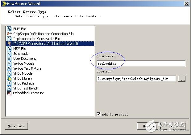
Figure 1 New IP core
Wait a moment, when the IP directory appears, select FPGA Features and Designà Clockingà Clocking Wizard, as shown in Figure 2, then click Next, then click Finish to wait for the Clocking Wizard configuration page to appear.
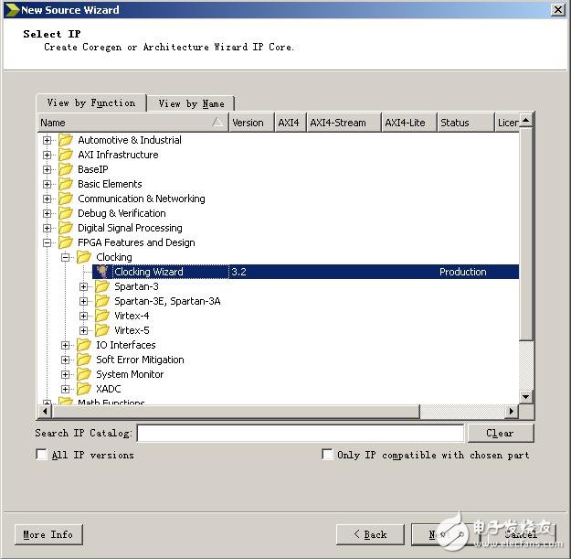
Figure 2 IP Directory
After the Clocking Wizard configuration page appears, open the corresponding interface signal as needed and enter the relevant parameters to complete the setup. Detailed reference to the several documents listed in the Clocking Wizard's menu Documents, as shown in Figure 3.
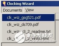
Figure 3 Clocking Wizard Reference Document
In this example, the input clock is simply set to 100 MHz, and four clocks of 100 MHz, 50 MHz, 25 MHz, and 12.5 MHz are output. The page1 and page2 are respectively set as shown in Fig. 4 and Fig. 5.
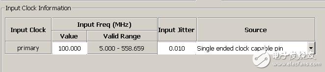
Figure 4 page1 input clock settings
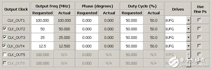
Figure 5 pgae2 output clock settings
After completing the above configuration, click the Generate button in the lower right corner to generate the IP core source code. When the message "INFO:ProjectMgmt - Parsing design hierarchy completed successfully." appears in the console window of ISE, the code generation has been completed. At this point, a new file named myclocking.xco appears below Hierarchy. If the file is selected, the CORE Generator function option shown in Figure 6 appears under Processes.
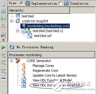
Figure 6 CORE Generator function options
The next thing we need to do is to instantiate myclocking into the top-level code, double-click View HDL InstanTIaTIon Template, and copy the HDL instantiation template (the following code snippet) to the top-level file. //----------- Begin Cut here for INSTANTIATION Template ---// INST_TAG myclocking instance_name (// Clock in ports .CLK_IN1(CLK_IN1), // IN // Clock out ports .CLK_OUT1( CLK_OUT1), // OUT .CLK_OUT2(CLK_OUT2), // OUT .CLK_OUT3(CLK_OUT3), // OUT .CLK_OUT4(CLK_OUT4), // OUT // Status and control signals .RESET(RESET),// IN .LOCKED (LOCKED)); // OUT// INST_TAG_END ------ End INSTANTIATION Template --------- In the top-level file, modify the signal interface (corresponding to the signal in parentheses) to match the actual interface. In this example, four different frequency clocks output by clocking are used to separately drive four LEDs to achieve the effect of four LEDs that do not use clock and counter frequency division. In addition, the other four LEDs are also driven by the two-way two-way signal. The user can observe that the brightness of the four LEDs is different. If the waveform of the corresponding IO output is measured by an oscilloscope, the frequencies are 50MHz and 25MHz, respectively. 12.5MHz and 6.25MHz. The modified top-level source code is as follows: module testled( clk,rst_n, led ); input clk; //100MHzinput rst_n; //low level reset signal output[7:0] led; //connected to LED indicator wire clk_100m //clocking output 100MHzwire clk_50m; //clocking output 50MHzwire clk_25m; //clocking output 25MHzwire clk_12m5; //clocking output 12.5MHzwire clk_locked; //clocking output completion flag ///---------- ----------------------------------------//IP core Clocking Wizard instantiation // ----------- Begin Cut here for INSTANTIATION Template ---// INST_TAG myclocking uut_myclocking (// Clock in ports .CLK_IN1(clk), // IN // Clock out ports .CLK_OUT1(clk_100m) , // OUT .CLK_OUT2(clk_50m), // OUT .CLK_OUT3(clk_25m), // OUT .CLK_OUT4(clk_12m5), // OUT // Status and control signals .RESET(!rst_n), // IN .LOCKED( Clk_locked)); // OUT// INST_TAG_END ------ End INSTANTIATION Template --------- //-------------------- -------------------------------reg[ 24:0] cnt0;//100MHz clock division counter always @ (posedge clk_100m or negedge rst_n) //Asynchronous reset if(!rst_n) cnt0 <= 25'd0; else cnt0 <= cnt0+1'b1;// Register cnt0 loop count assign led[0] = cnt0[24]; //--------------------------------- ------------------reg[23:0] cnt1; // 50MHz clock division counter always @ (posedge clk_50m or negedge rst_n) / / asynchronous reset if (! rst_n Cnt1 <= 24'd0; else cnt1 <= cnt1+1'b1;//register cnt1 loop count assign led[1] = cnt1[23]; //------------- --------------------------------------reg[22:0] cnt2;//25MHz clock The crossover counter always @ (posedge clk_25m or negedge rst_n) / / asynchronous reset if (! rst_n) cnt2 <= 23'd0; else cnt2 <= cnt2 + 1 'b1; / / register cnt2 loop count assign led [2] = Cnt2[22]; //------------------------------------------- --------reg[21:0] cnt3;//12.5MHz clock division counter always @ (posedge clk_12m5 or negedge rst_n) //Asynchronous reset if(!rst_n) cnt3 <= 22'd0; else Cnt3 <= cnt3+1'b1; / / register cnt3 loop count assignment led [3] = cnt3[21]; //--------------------------------------- ------------//4 clocking output clock 2-way register for oscilloscope observation assign led[7:4] = {cnt0[0],cnt0[1],cnt0[2 ], cnt0[3]}; endmodule Hierarchy select the top source code testled.v, then double-click the Generate Programming File under Processes to compile and produce the burned file. When the "Process "Generate Programming File" completed successfully" message appears in the Console, you can open Digilent Adept and use the Config function to burn the newly generated testled.bit file. Reprinted from: privileged classmate's blog
Crane Scale
GALOCE Various products of Crane Scale, hanging scale, providing product images and basic parameters with each Electronic Crance Scale and Digital Crane Scale; We are a professional Chinese manufacturer of Crane Scale, Wireless Load Cell, and Wireless Dynamometer, and look forward to your cooperation!
Crane Scale,Crane Weight Scale,Crane Load Cell,wireless dynamometer
Xi'an Gavin Electronic Technology Co., Ltd , https://www.galoce-meas.com
