
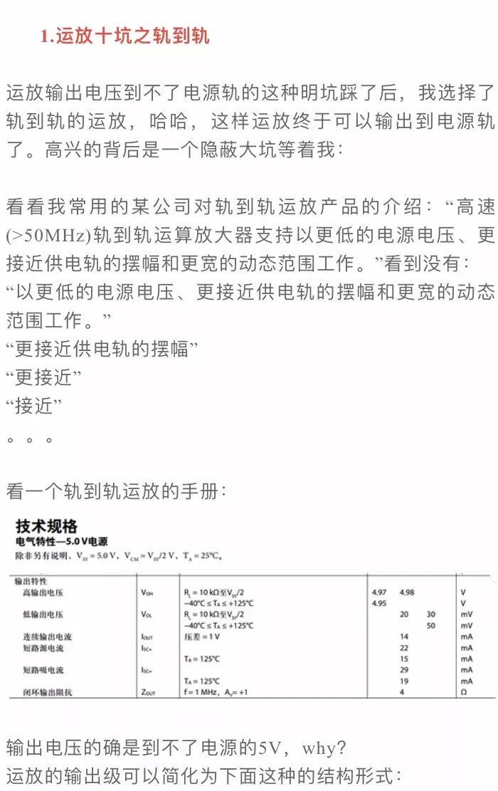
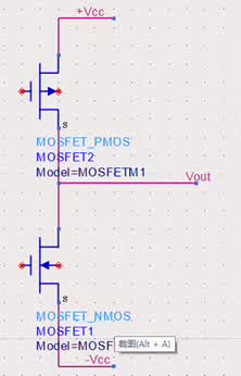
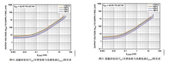
Since the MOS transistor has an on-resistance, when current flows through it, a voltage drop occurs. This means that as the load increases, the on-state voltage drop also increases, which reduces the output voltage and makes it less likely to reach the power supply rail.
Therefore, even a rail-to-rail op amp cannot always achieve the full power supply voltage at its output. When using such an op amp, it's essential to consider the relationship between the load and temperature, as both can affect the on-resistance and thus the maximum achievable output voltage.
2. Input Bias Current of Op Amps Can't Be Ignored
A voltage divider circuit was designed with the intention of achieving an output of 2V from an input of 1V. However, during testing, the output consistently exceeded 6.7 mV, which was problematic for a 12-bit ADC operating at 3V. The issue stemmed from the input bias currents of the op amp, which caused an offset error.
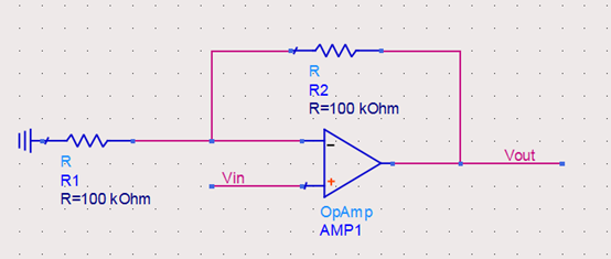
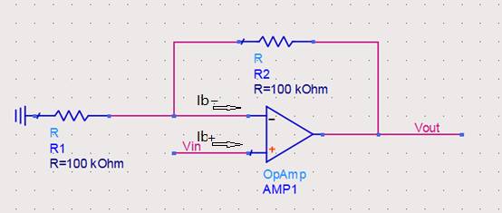
The positive and negative inputs of the op amp generate different input bias currents due to TVS leakage and internal transistor characteristics. These currents create a bias voltage across external resistors, leading to an error in the output signal. If a BJT-based op amp is used, the large input bias current will result in significant errors, making the circuit unstable or inaccurate.

Assuming the input bias currents are equal, the calculation shows that the non-inverting input sees almost no bias voltage, while the inverting input may have a bias voltage of around 350mV. To compensate, a resistor should be added to the non-inverting input to balance the error caused by the inverting side.
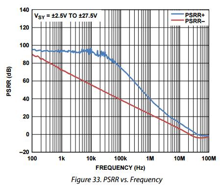
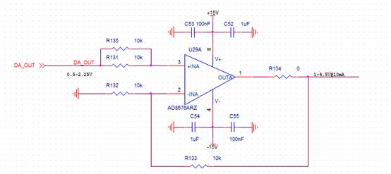
Even if the supply voltage varies between 4.5V and 5.5V, the effect on the op amp’s output is minimal—only about 10nV. However, this figure refers only to DC changes, not AC ripple. In AC scenarios, the PSRR (Power Supply Rejection Ratio) degrades significantly, which can lead to larger errors in the output signal.
If a switching power supply is used without proper decoupling and filtering, the noise can severely impact the accuracy of the op amp’s output. As shown in the graph, the PSRR at 500kHz drops to 50dB, meaning a 100mV ripple could translate into a 0.3mV error. For precision applications, this is often unacceptable, so some systems use low-pass filters at the power input of the op amp (while considering resistor power and thermal noise).
4. Compensation Capacitors in Op Amp Circuits
In the past, I believed that adding a small capacitor to the feedback path would prevent oscillation. But later, I realized that this wasn’t always necessary. For example, when amplifying a 100kHz signal, a feedback capacitor reduced the impedance below 200Ω, altering the gain and causing distortion.
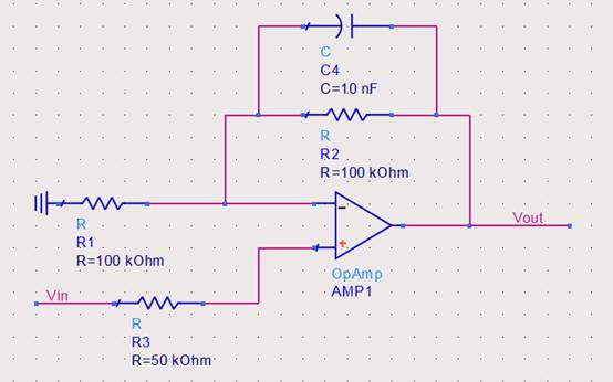
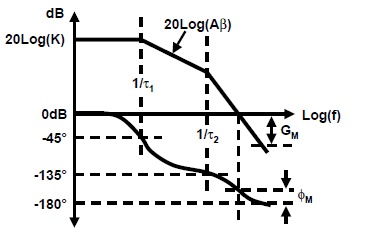
Op amps have internal poles that cause phase shifts, potentially leading to instability. Adding another pole can worsen the phase shift, making oscillation more likely. However, in many cases, the op amp already has sufficient phase margin, and extra compensation capacitors are unnecessary.

When the loop gain Aβ equals 1 at -180° phase shift, the circuit becomes unstable. External zeros, like those from parasitic capacitance, can cause oscillation. Adding a capacitor introduces a zero that helps stabilize the system, but it’s important to check the datasheet first.
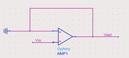
For a follower circuit, the input voltages are nearly equal, but if the input approaches the power supply rails, the op amp may enter saturation, losing linear behavior. This is similar to a transistor amplifier reaching its saturation point, where further input changes don’t produce proportional output changes.
6. Slew Rate of Op Amps Should Not Be Overlooked
When designing a 1pps driver with a rising edge ≤5ns, the op amp failed to meet the requirement despite being followed by a driver circuit. The problem was the slew rate—the rate at which the output voltage can change in response to a step input.
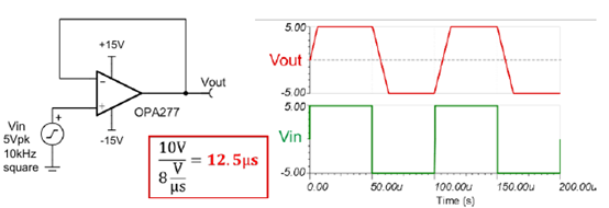
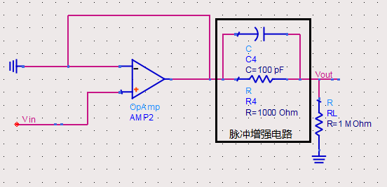
The op amp’s slew rate was too slow to handle the required edge, resulting in a distorted output. To solve this, a pulse boost circuit was added, consisting of a differentiator and a DC resistor, which improved the rise time significantly.
7. Forgotten Feedback Resistor in Op Amp Circuits
Adding a current feedback amplifier (CFA) to increase drive capability seemed straightforward, but it didn’t work as expected. The issue was that CFAs behave differently from voltage feedback amplifiers (VFAs). Without a feedback resistor, the CFA couldn’t function properly, leading to no output signal.
CFAs have a very low input resistance at the inverting terminal and a transimpedance gain close to 1. This requires a feedback resistor to set the closed-loop gain correctly. Without it, the circuit fails to operate as intended.

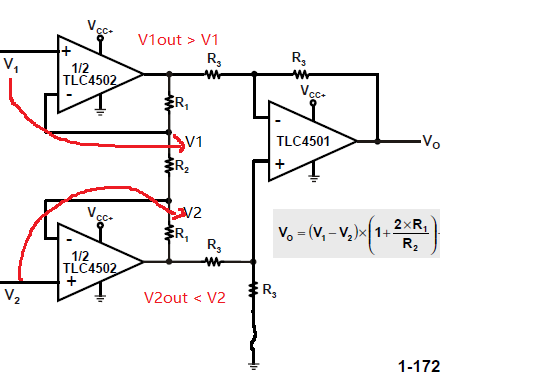
8. Input Range and Output Limitations in Instrumentation Amplifiers
An instrumentation amplifier circuit appeared to be well-designed, with proper power supply, gain, and input range. However, at high input voltages, it failed to function correctly. This was because the internal structure of the instrument amplifier required a higher voltage than the power supply could provide, causing saturation and incorrect outputs.
9. Op Amp Delay Affects ADC Sampling
ADC sampling issues were traced back to the op amp’s delay. Even though the ADC had a fast acquisition time, the op amp’s settling time and oscillation caused the sampled data to be unstable. This was especially true when the PCB layout introduced additional delays and noise.
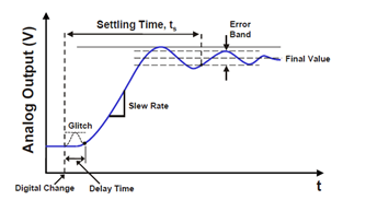
The op amp’s settling time was longer than expected, leading to errors in the ADC readings. Reducing the sampling rate and increasing the acquisition time helped stabilize the results.
10. Power Consumption of Op Amps Is Often Overlooked
During a power budget analysis, the op amp’s power consumption was underestimated. While static power was considered, the dynamic power due to the voltage difference between the supply and output was ignored. This led to a power over-consumption issue that was only resolved by using a lower supply voltage.
We offer a premium quality range of 520 mm Width Swan Neck Type Radiator in the market. This is sturdily fabricated using superior grade material and modern machinery in sync with set industrial norms and standards. 520 mm Width Swan Neck Type Radiator is known for its high efficiency, easy installation, low maintenance and better durability. This makes it stand apart from other radiators in the market. We offer this at highly pocket- friendly prices within a stipulated period of time.
Swan neck type of radiators are accessible with bend pipes at space restraint areas and can be made accessible with or without inserted sections provisional on the heat dissipation and oil quantity needed.
Swan Neck Radiator,Leakage Proof Swan Neck Radiator,Weather Proof Swan Neck Radiator,Anti Corrosion Swan Neck Radiator
Shenyang Tiantong Electricity Co., Ltd. , https://www.ttradiator.com