
The MCU (Microcontroller Unit) interface circuit consists of four pins: INH, SR, DO, and MS. The INH pin is used to select a low level under MCU control. SR serves as the data input terminal, while DO is the data output. Each bit of the data input or output is determined by the clock signal from the MS pin.
During the writing process controlled by the MCU, a command is sent to the language processor. Data is input through the SR terminal, and the INH terminal remains low when the MS terminal is active. When the MS terminal transitions from high to low, the SR terminal becomes valid for data input. The write command is a 4-bit instruction that includes an 8-bit control word or a 16-bit termination address, with the 10-bit start address corresponding to the address counter.
For reading under MCU control, after sending the read command to the language processor, the first byte of data is obtained from the DO terminal. Each subsequent byte is read on the rising edge of the MS signal. The read command can be used to access the status register, extended address counter, or regular address counter.
Manual and MCU control mode selection: After power-on, the FC9201 language processor starts in manual control mode, triggered by a reset signal on the RT pin. To switch to MCU control, a negative pulse is applied to the INH pin. This mode remains active during the pulse. To return to manual control, a negative pulse is sent to the RT pin, and the INH pin returns to a high level. The system alternates between manual and MCU modes after power-on, and the MCU state detection word does not need to be rewritten repeatedly.
External memory compression technology: To optimize DRAM usage, the compression mode is set via the MCS bit in the state control word. The PD1 and PD2 bits determine the compression parameters. The SEN1 and SEN2 bits are used to trigger valid or invalid language outputs based on the signal level.
External memory capacity: A single group of DRAM can reach up to 4Mbit. With 64-level extended pulse output, the total capacity becomes 64 × 4Mbit. At a sampling rate of 16kHz, the recording or playback time exceeds 4 hours.
Low-pass filter cutoff frequency selection: When the BW bit in the state control word is 0, the cutoff frequency is 3.4kHz; when it's 1, it's 2.7kHz. In manual control mode, at 16kHz, the cutoff is 2.7kHz, and at 32kHz, it’s 3.4kHz.
Rate selection: When the external clock is 3.58MHz, the rate can be set to either 16kHz or 32kHz. Changing the external clock frequency allows for different rates. For example, using a 5.5MHz clock changes the original 16kHz rate to 24kHz.
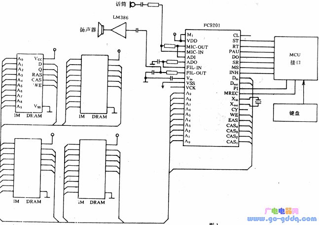
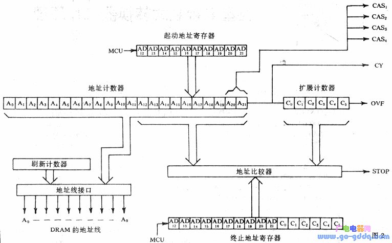
Application of FC9201: The figure shows a typical electrical schematic of the FC9201. It is directly controlled by a microprocessor, using a 4-pin interface (INH, SR, MS, DO) for operations such as starting, ending, and setting addresses. Status registers store commands like the start address, control word, and end address. The internal address mapping is shown in the diagram below, allowing the microprocessor to freely record or play back audio from different DRAM regions.
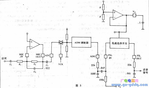
The analog section of FC9201 includes microphone amplification, ADM filtering, and modulation/demodulation. The microphone amplifier is a Class I op-amp, with gain adjustable via R2/R1 and frequency characteristics adjusted using R2 and C2. Its typical bandwidth is 3.4kHz. The ADM input impedance is about 25kΩ, and a coupling capacitor C3 helps suppress 50Hz or 60Hz hum at a 300Hz cutoff. To minimize distortion, the ADM input signal should stay within 2V peak-to-peak. The ADO signal, which is a D/A conversion plus 1/2 VDD, goes through a low-pass filter and is converted into an audio signal via RC filtering at FILOUT. This signal is then amplified by an LM386 and sent to the speaker.
Servo Electric Cylinder,Linear Actuator With Speed Control,Parallel Drive Linear Actuators,Long Stroke Electric Linear Actuator
Suzhou Johnson Automation Technology Co., Ltd. , https://www.cn-johnson.com