
Disaster search and rescue has always been an important application area for drones and robots. Japan is a country with advanced robot technology and frequent earthquake and tsunami disasters. Recently, researchers from Osaka University, Kobe University, Tohoku University, Tokyo University and Tokyo Institute of Technology have developed a construction robot for disaster search and rescue. It can improve operability and mobility completely compared to traditional construction machinery.
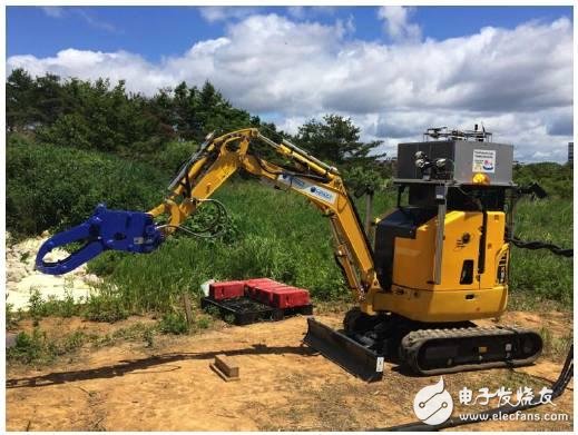
Construction robot prototype (image from: Osaka University)
Exterior:
sketch:
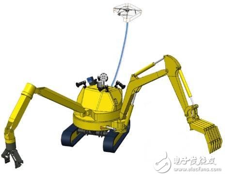
Conceptual sketch of the construction robot (Image courtesy of Osaka University)
When conducting an experiment:
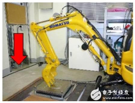
A snapshot of the vertical push experiment on the experimental platform of Kobe University (Image courtesy of Osaka University)
Analysis of key technical points
This type of disaster search and rescue building robot, and the key technologies used in it, are designed to address the challenges of traditional construction machinery in disaster environments. Below, let's talk about several representative basic technologies of the robot:
Fine-tune the position and speed, control the pressure of the high-speed cylinder to reach the target value, and quickly and stably control the large inertia machine.
The hydraulic pressure of each hydraulic cylinder is evaluated to measure the external load of a multi-degree of freedom (DOF) hydraulic transmission robot. In order to remotely search and rescue robots, the strength is evaluated for strength control or force feedback.
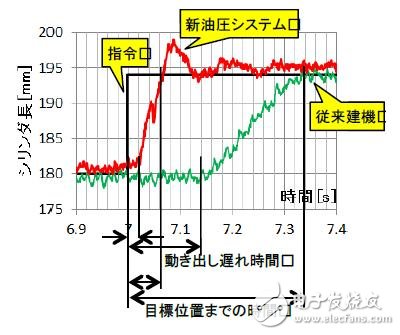
Dynamic response diagram of a robot arm robot using a new hydraulic control system (Photo: Osaka University)
The high-frequency vibration is measured by the force sensor mounted on the robot's distal actuator, and the tactile vibration is fed back to the operator.
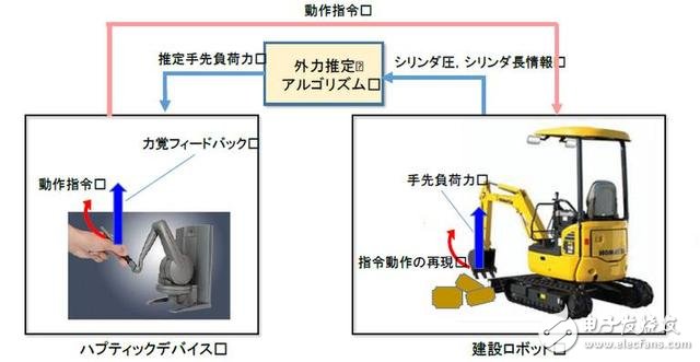
Dynamic feedback system (Image courtesy of Osaka University)
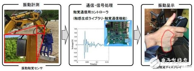
Example of a tactile information transmission system using vibration (Source: Osaka University)
Image information is acquired by a multi-rotor aircraft (unmanned aerial vehicle) at a location selected by the Feida operator. The apron through the power line and power feedback allows the drone to fly long distances and accurately land.
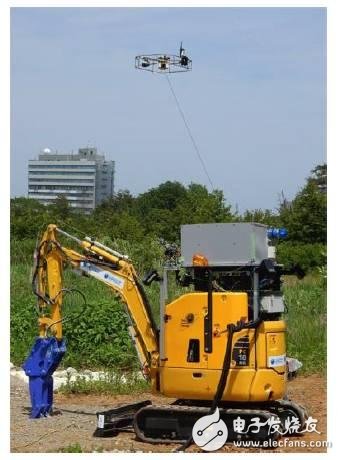
Drones caught by the line (Image courtesy of Osaka University)
Four fisheye cameras are installed on the drone, allowing you to view the top view of any place in real time and evaluate the environment around the robot.
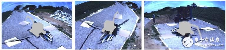
Real-time visualization of architectural robots from any perspective (Image courtesy of Osaka University)
The robot uses a near-infrared camera to observe long-wave light. Therefore, the operator can operate the robot to evaluate the environment even in bad weather conditions such as fog or hail.
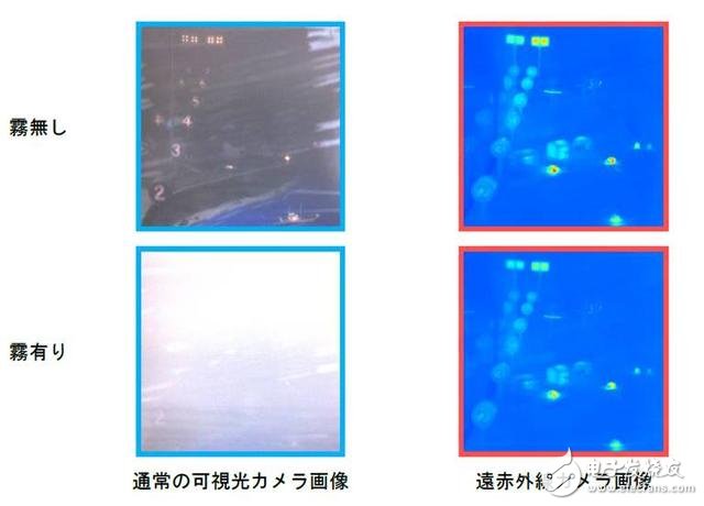
Normal visible camera and long-wave infrared (LWIR) camera contrast in clear and foggy environments. (Image courtesy of Osaka University)
Future prospects
At the same time, the researchers conducted verification experiments at representative disaster sites, and the current functions have been verified to some extent. In addition to the several technologies mentioned above, the research team is also developing several other key technologies to improve technical performance. They are also developing new robots with dual rotation mechanisms and dual arms for higher operability and terrain adaptability.
Product Description
SPD Surge Protective Device,Lightning Surge Protector
Surge Protection Device (SPD)
It is a device used to limiting instant surge voltage and discharge surge current, it at least including a non-linear component.
Surge protective Device Model Selection
With the impact of international information flow, the rapid development of microelectronic science and technology, communication, computer and automatic control technology, make the building start to go for high quality, high functional area, formed a new building style-intelligent building. As inside the intelligent building there are lot of information system, <<Building lightning protection design norm>> GB50057-94(2002 vision)(hereafter brief as <<lightning protection norm>>) put forward the relative requirement to install the surge protective device, to ensure the information system safely and stable running.
SPD essentially is a equipotential connection material, its model selection is according to the different lightning protection area, different lightning electromagnetic pulse critical and different equipotential connection position, decide which kind of SPD used in the area, to achieve the equipotential connection with the common earth electrode. Our statement will based on SPD's maximum discharge current Imax, continuous operating voltage Uc, protection voltage Up, alarm mode etc.
As per << Lightning Protection Norm>> item 6.4.4 stipulation "SPD must can withstand the expected lightning current flow and should confirm to the additional two requirements: the maximum clamp voltage during surge across, capable to extinguish the power frequency follow-on current after lightning current across." That is the value of SPD's max. clamp voltage add its induction voltage of two ends should be same with the system's basic insulation level and the equipment allowed max. surge voltage.
SPD for Power Supply System Series Selection Guide
The installation of SPD at each lightning protection zone, according to the standard of low voltage electrical appearance, make classification of electrical equipment in accordance with the over voltage category, its insulation withstand impulse voltage level can determine the selection of SPD. According to the standard of low voltage electrical appearance, make classification of electrical equipment in accordance with the over voltage category as signal level, loading level, distribution and control level, power supply level. Its insulation withstand impulse voltage level are:1500V,2500V,4000V,6000V. As per to the protected equipment installation position different and the different lightning current of different lightning protection zone, to determine the installation position of SPD for power supply and the break-over capacity.
The installation distance between each level SPD should not more than 10m, the distance between SPD and protected equipment should as short as possible, not more than 10m. If due to limitation of installation position, can't guarantee the installation distance, then need to install decoupling component between each level SPD, make the after class SPD can be protected by the prior class SPD. In the low voltage power supply system, connecting an inductor can achieve the decoupling purpose.
SPD for power supply system specification selection principle
Max. continuous operating voltage: bigger than protected equipment, the system's max. continuous operating voltage.
TT System: Uc≥1.55Uo (Uo is low voltage system to null line voltage)
TN System: Uc≥1.15Uo
IT System: Uc≥1.15Uo(Uo is low voltage system to line voltage)
Voltage Protection Level: less than the insulation withstand impulse voltage of protected equipment
Rated discharge current: determined as per to the lightning situation of the position installed and lightning protection zone.
SP1 Series
Normal Working Conditions
-Altitude not exceed 2000m
-Ambient air temperature:
Normal range: -5ºC~+40ºC
Extend range: -40ºC~+80ºC
-Relative Humidity: 30% - 90% under indoor temperature condition
- At the place without obviously shaking and shock vibration
- Non-explosion danger medium, non-corrosion gas and dust ( including conductive dust)
Classification
-As per Nominal Discharge Current:
5,10,20,30,40,60KA(8/20µs)
- As per Maximum continuous operating voltage:
275V,320V,385V,420V,440V,460V
- As per to poles
1P,1P+N,2P,3P,3P+N,4P
- As per auxiliary functions:
a. With remote signal output ( remote alarm function)
b. Without remote signal output
Selection Principle
- The continuous applied voltage on the two terminals of SPD should not more than the maximum continuous operating voltage Uc value;
- The voltage protection level Up of SPD should less than the maximum impulse withstand voltage of the protected equipment;
- As per to the different earthing system and protection mode to select the specification accordingly;
Product Features
1, built-in over-current overheating, temperature control circuit technology.
2, the module design, easy installation, online replacement.
3, low leakage current, fast response time, low residual voltage.
4, alarm indication device, green (normal) v red (fault).
| Model/Technical Parameters | WR-B60 | WR-B80 | WR-B100 | WR-B120 | WR-B150 |
| Rated Operating Voltage Un (V ~) | 220V 380V | 220V 380V | 220V 380V | 220V 380V | 220V 380V |
| Maximum Continuous Operating Voltage Uc (V ~) kV | 385V 420V | 385V 420V | 385V 420V | 385V 420V | 385V 420V |
| Voltage Protection Level Up (V ~) kV | ≤1.8≤2.2 | ≤2.4≤2.5 | ≤2.5≤3.2 | ≤3.4≤3.7 | ≤4.0≤4.5 |
|
Maximum Discharge Current Imax(8/μ20μs)kA |
60 | 80 | 100 | 120 | 150 |
|
Nominal Discharge Current In(8/μ20μs)kA |
30 | 40 | 60 | 80 | 100 |
| Response Time | <25 | <100 | |||
| L/N(mm²)The Cross Section Of L/N Line | 16,25 | 16,25 | 16,25 | 16,25 | 25,35 |
| PE (mm²)The Cross Section Of PE Line | 16,25 | 25,35 | 25,35 | 25,35 | 35 |
| Fuse or Switch (A) | 63A | 63A | 63A,100A | 63A,100A | 63A,125A |
| The Line Section of Communication and Alarm (mm²) | ≥ 1.5 | ||||
|
Operating Environment-C |
(-40ºC~-+85ºC) | ||||
| Relative humidity 25 ºC | ≤95% | ||||
| installation | Standard Rail35mm | ||||
| Material of Outer Covering | Fiber Glass Reinforced Plastic | ||||
Surge Protector SPD,Surge Protection Device SPD,SPD
Wenzhou Korlen Electric Appliances Co., Ltd. , https://www.zjmannualmotorstarter.com